


Transformer Core Engineering Notes · CF-N288
A flexible connection is not a force-free connection. Its geometry, material and support arrangement determine how it responds to movement and what it transmits to a transformer bushing. Specify electrical capability and mechanical behavior together, including the installed shape, instead of assuming any braided or laminated connector will protect the terminal automatically.
Define the required movement
Identify thermal expansion, construction tolerance, relative equipment movement and other applicable demands. State the direction and range of movement, not just a single displacement magnitude. A connector may be compliant in one direction and comparatively stiff in another. The selected arrangement must be assessed in its installed orientation with the surrounding supports, rather than judged from how easily an uninstalled sample bends by hand.
Connect stiffness to terminal force
For a simplified linear illustration, force equals stiffness multiplied by displacement. Real connectors may have direction-dependent or nonlinear behavior, so use the supplier’s applicable data and model. The purpose of the illustration is to show why allowing movement does not imply zero transmitted load. Compare the resulting forces and moments with the OEM’s limits for the actual bushing and mounting arrangement.
Preserve current and clearance requirements
A mechanically compliant shape still needs adequate current capability, connection quality and electrical clearance throughout the permitted movement. Adjacent phases or grounded parts must not become conflicting boundaries. Fault forces and the retention of individual elements also need the appropriate design review. Do not increase flexibility by an unapproved alteration that changes the connector’s tested or specified electrical construction.
Install within the approved geometry
The installation drawing should specify the connector orientation, support points and permitted initial position. A connector installed at the end of its movement range may have little useful allowance left. Resolve misalignment through the approved engineering process rather than forcing the bushing or permanently deforming the connector. Record the final geometry so later replacement preserves the intended mechanical and electrical behavior.
| Review item | Evidence to request | Boundary to preserve |
|---|---|---|
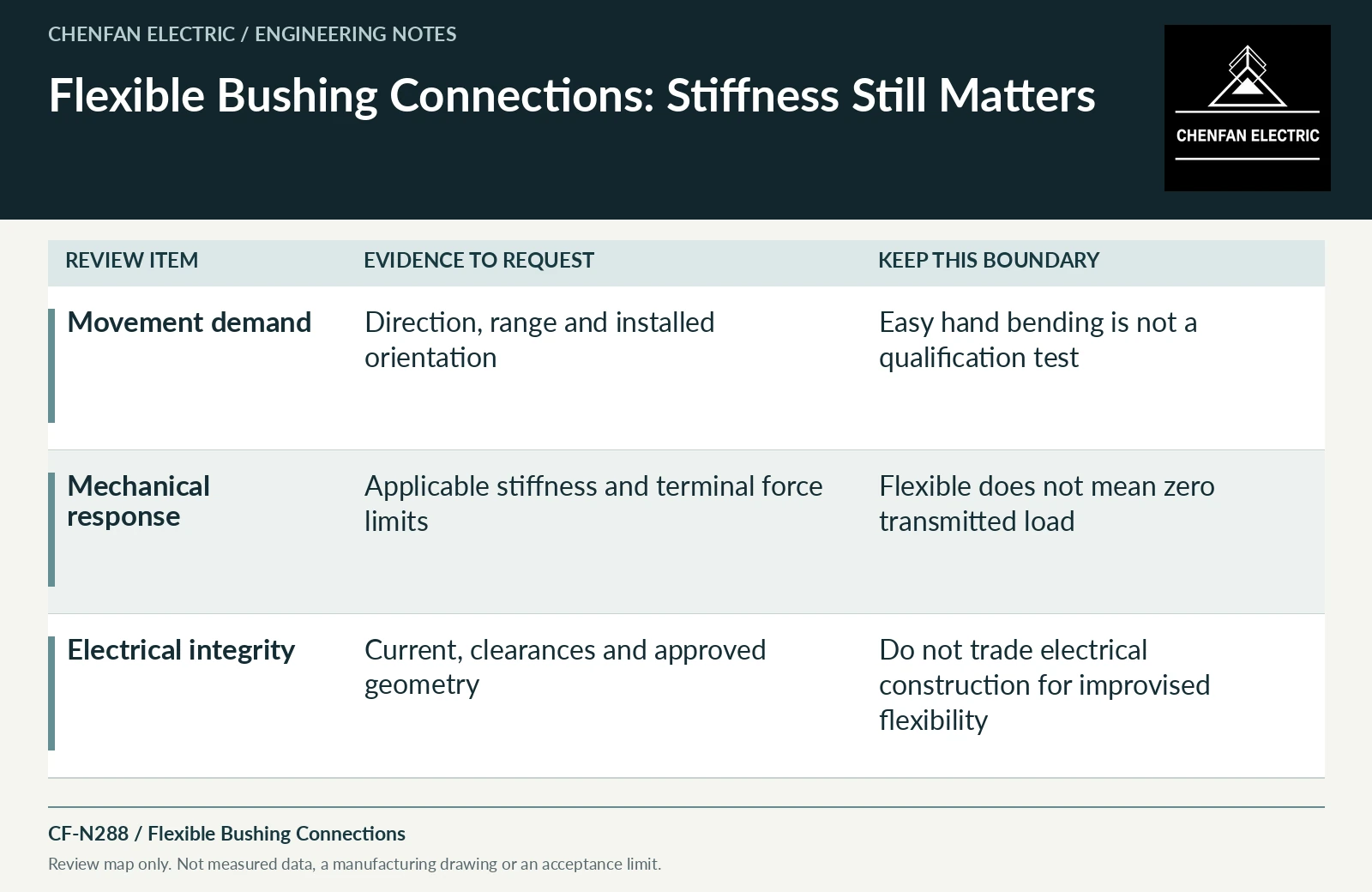
| Movement demand | Direction, range and installed orientation | Easy hand bending is not a qualification test |
| Mechanical response | Applicable stiffness and terminal force limits | Flexible does not mean zero transmitted load |
| Electrical integrity | Current, clearances and approved geometry | Do not trade electrical construction for improvised flexibility |
References and scope
- Bushing Maintenance (FIST 3-2)Historical technical manual · Bushing components, connection and maintenance interfaces.
- Electrical Connections for Power Circuits (FIST 3-3)Historical technical manual · Electrical-joint and connection principles; not a universal torque table.
- IEC 60076-3:2013+AMD1:2018 CSV — Insulation levels and dielectric testsPublic standard abstract · Insulation levels, dielectric testing and external clearances; the article does not reproduce test values or design distances.