

Dimensional interchangeability answers whether an accessory can be installed. Seismic equivalence also depends on mass distribution, stiffness, restraint and the loads entering the connection. An accessory substitution should therefore be compared with the configuration covered by the existing qualification basis. [1] [2]
Create a controlled old-to-new comparison
Identify the qualified assembly and the actual installed revision. Compare accessory mass, center coordinates, mounting geometry, material and support stiffness. Retain changes in connected piping or conductors, since the replacement can alter those mechanical boundaries even when its footprint is unchanged.
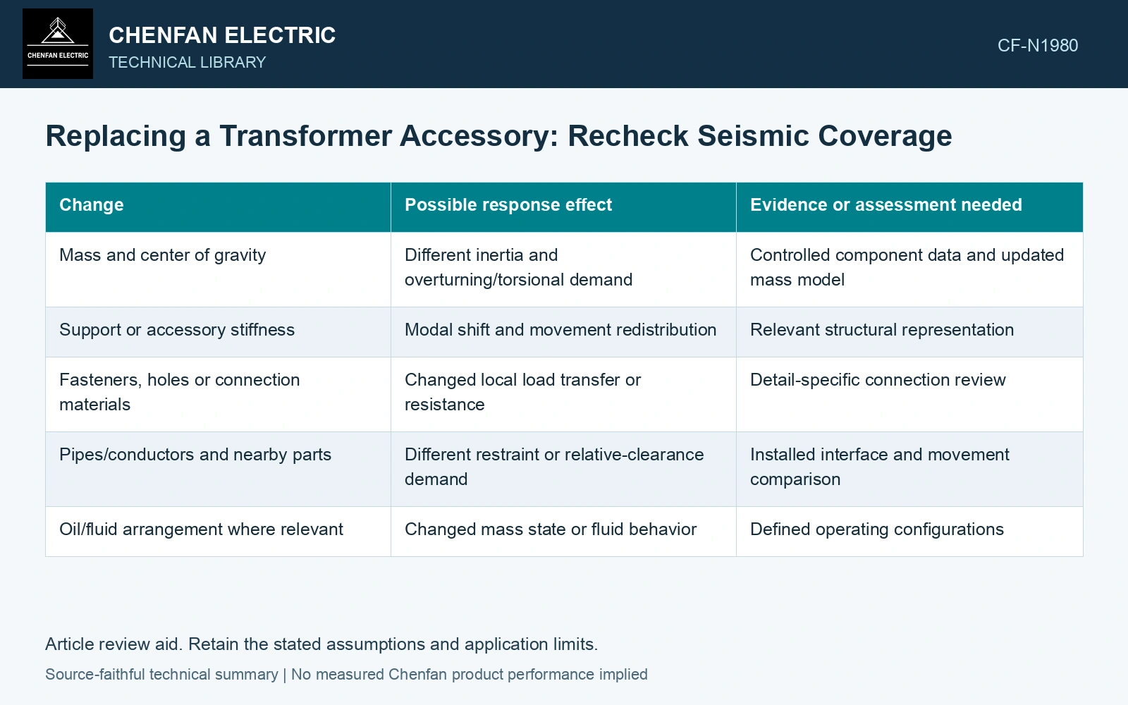
| Change | Possible response effect | Evidence or assessment needed |
|---|---|---|
| Mass and center of gravity | Different inertia and overturning/torsional demand | Controlled component data and updated mass model |
| Support or accessory stiffness | Modal shift and movement redistribution | Relevant structural representation |
| Fasteners, holes or connection materials | Changed local load transfer or resistance | Detail-specific connection review |
| Pipes/conductors and nearby parts | Different restraint or relative-clearance demand | Installed interface and movement comparison |
| Oil/fluid arrangement where relevant | Changed mass state or fluid behavior | Defined operating configurations |
Check the existing qualification boundary
Read the actual report or approved basis for the configuration and modifications it covers. Do not infer an allowable substitution solely from the report title or a generic seismic standard reference. Where coverage is uncertain, record the gap rather than describing the replacement as equivalent.
An accessory change may require only a local comparison, or it may influence the supporting transformer modes. Evaluate that distinction from the change in mass, stiffness and coupling. A percentage change in accessory weight alone is not a universal rule for selecting the assessment scope.
Carry changed demand into unchanged parts
The mounting bracket, tank panel or anchor may remain physically unchanged while receiving a different demand. Update the connection checks where the assessment indicates redistribution. Also examine whether changed movement reduces a mechanical gap or affects the required electrical clearance.
Keep the supporting data traceable to the replacement revision. If its internal design or center of gravity is unavailable, matching external dimensions does not resolve that uncertainty. Seek the relevant information or use an approved conservative assessment with its limits documented.
Assume a replacement accessory increases mass from 40 kg to 60 kg while retaining a 0.50 m centre-of-mass height above its mounting plane. Under an assumed 1.0g horizontal acceleration screen, inertia force rises from 392.4 N to 588.6 N and overturning moment from 196.2 to 294.3 N·m. The 50% increase is not covered merely by retaining the same bolt pattern. Recheck the accessory, attachment and supporting tank region against the qualification configuration before accepting the substitution.
Close the substitution record with the differences assessed, evidence used, affected connections and qualification coverage decision by the responsible parties. Include any updated installation controls. This gives maintenance and project teams a usable change record without treating “fits in place” as a seismic acceptance statement.
References
- FEMA and Applied Technology Council, FEMA E-74, Reducing the Risks of Nonstructural Earthquake Damage—A Practical Guide, December 2012, section 6.4.7.3, Transformers.
- IEEE, IEEE 693-2018, IEEE Recommended Practice for Seismic Design of Substations.