

At one balanced sinusoidal port, lower active power can leave current capacity for reactive exchange [1]. An SST still needs topology-specific voltage/current, thermal and loss-supply qualification [2]; a spare kW number is not a continuous kvar rating.
Low active transfer is a possible operating opportunity, not proof of unrestricted reactive capacity.
Start with the port current boundary
For a balanced sinusoidal three-phase port, Smax = √3 VLLImax and P²+Q²≤Smax² [1], with V, A, VA, W and var. This current-only circle omits modulation, temperature, harmonics, unbalance and internal-stage constraints.
The circle omits modulation, thermal, harmonic, unbalance and internal-stage constraints. It is a transparent first boundary, not a complete SST capability curve.
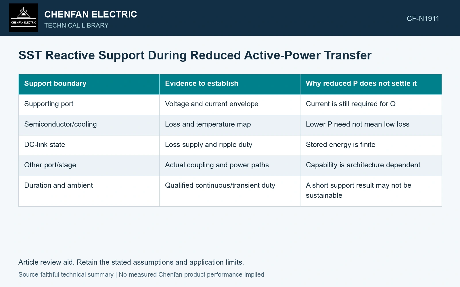
| Support boundary | Evidence to establish | Why reduced P does not settle it |
|---|---|---|
| Supporting port | Voltage and current envelope | Current is still required for Q |
| Semiconductor/cooling | Loss and temperature map | Lower P need not mean low loss |
| DC-link state | Loss supply and ripple duty | Stored energy is finite |
| Other port/stage | Actual coupling and power paths | Capability is architecture dependent |
| Duration and ambient | Qualified continuous/transient duty | A short support result may not be sustainable |
Provide energy for the losses
Ideal reactive exchange has no net active energy transfer over a cycle, but real equipment losses need an energy source. If the input is unavailable, a DC link or another qualified port may supply those losses for a bounded interval.
Do not describe reactive support as energy free. A link energy balance can drift because of losses even when commanded active output is zero. Maintaining voltage and protection headroom remains part of the duty.
Separate input and output capabilities
An input converter can support its grid while an output converter performs another service. The isolated stage and link controls determine their interactions. A reactive rating at one port cannot be copied to the other by assuming that both endpoints have identical hardware.
The conversion-stage review locates power-factor correction, voltage regulation and isolated transfer within specific topologies [2]. Build the requested port’s Q map, then follow current, temperature and loss supply through every supporting stage.
Qualify the requested operating region
Assess representative combinations of active power, reactive command, voltage and thermal condition. Include control saturation and the approved response when a limit is reached. A single low-P test point cannot establish the full support region.
Assume a balanced 400 V port with 200 A RMS current limit. Apparent-power limit is 138.56 kVA. At 120 kW, ideal remaining reactive magnitude is √(138.56² − 120²) = 69.28 kvar. Reducing active transfer to 80 kW raises that ideal current-only margin to 113.14 kvar. These are assumed port-envelope results, not converter ratings: semiconductor temperature, modulation and DC-link energy may constrain the actual dispatch sooner. Verify those limits before promising voltage support at low active load.
At lower P, the requested Q still has to fit the supporting port’s current limit and the internal temperature and loss-supply envelope. If port voltage or cooling changes, that headroom has to be reassessed for the required duration. Spare active-power capacity alone is insufficient grounds for a continuous reactive-support rating.
References
- U.S. Department of Energy, DOE-HDBK-1011/4-92, Electrical Science, Volume 4, 1992.
- D.-M. Predescu and Ș.-G. Roșu, Solid State Transformers: A Review—Part I: Stages of Conversion and Topologies, Technologies 13, 74, 2025. DOI: 10.3390/technologies13020074.