

Three SST phase clusters can deliver the required total power while one cluster’s DC-link voltage drifts. The total terminal balance does not guarantee that each internal energy state is balanced. Unequal load allocation, losses or input conditions can create a local deficit.
The assessment should retain a ledger for each cluster and identify the physical path through which the imbalance can be corrected. A controller cannot redistribute energy through a path the topology does not provide.
Separate average energy and oscillating power
For cluster k, dEk/dt = Pin,k−Pout,k−Ploss,k in J and W. For an assumed constant linear capacitance, integrating V dQ with Q=CV [1] gives E=½CV². Average power imbalance changes energy; zero-mean ripple can still change voltage cyclically.
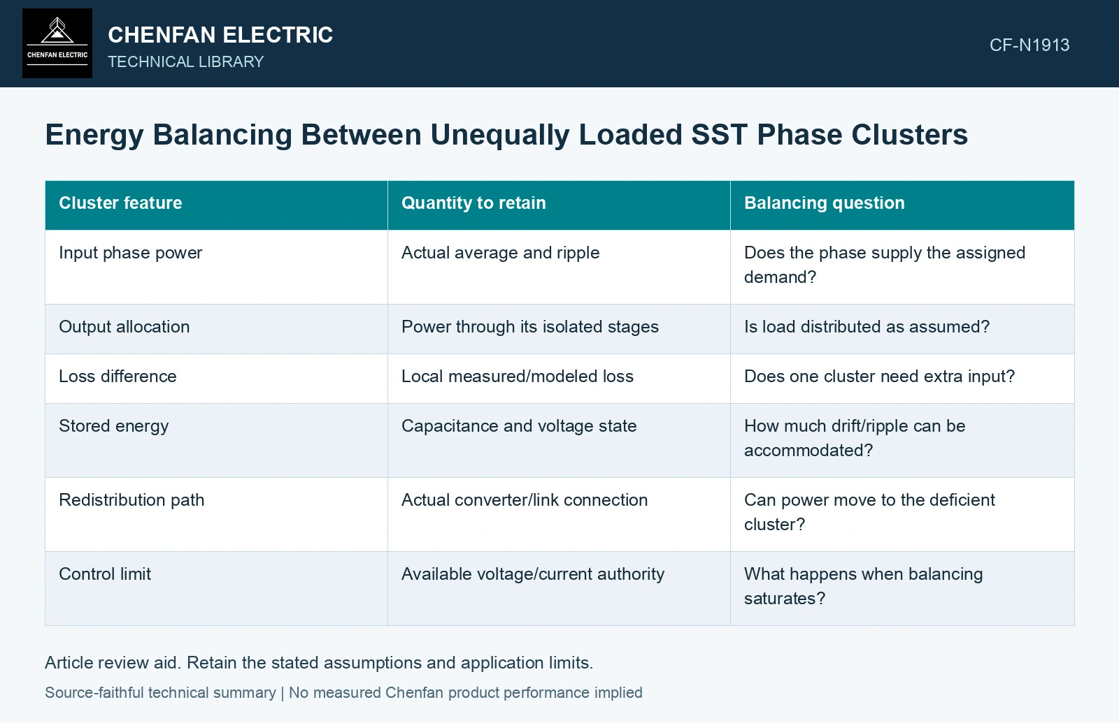
| Cluster feature | Quantity to retain | Balancing question |
|---|---|---|
| Input phase power | Actual average and ripple | Does the phase supply the assigned demand? |
| Output allocation | Power through its isolated stages | Is load distributed as assumed? |
| Loss difference | Local measured/modeled loss | Does one cluster need extra input? |
| Stored energy | Capacitance and voltage state | How much drift/ripple can be accommodated? |
| Redistribution path | Actual converter/link connection | Can power move to the deficient cluster? |
| Control limit | Available voltage/current authority | What happens when balancing saturates? |
Check the architecture’s transfer route
Some modular arrangements feed a common LV DC bus through isolated cells. Others have different link and phase structures. The common bus can provide a route for output allocation only within the actual converter capability. It does not guarantee unlimited cluster-to-cluster balancing.
The conversion review describes the modular stages and link arrangements [2]. Map each cluster’s actual transfer route and retain individual voltage/current limits; total-system power cannot establish equal local stored energy.
Test the imbalance that total measurements hide
Assess unequal input voltages, asymmetric loads, cell loss differences and sensor offsets where credible. Record individual link states during transients and steady operation. A correct total output reading cannot reveal every internal overvoltage or depleted-energy state.
Keep phase imbalance distinct from cell imbalance within a phase. The controls can interact, but they have different energy boundaries and may reach different limits.
Validate limit handling
A balancing command can consume current or voltage margin needed by normal transfer. Include that demand in the operating envelope. If a cluster reaches its limit, the approved scheme needs a defined reduced or inhibited service state.
Assume one cluster loses 5 kW for 20 ms: deficit is 100 J. With 2 mF initially at 800 V, final ideal voltage is 734.85 V. An assumed 750 V floor permits only 77.5 J, corresponding to 15.5 ms at that deficit. Hold a proposed 20 ms balancing response or provide additional accessible energy/power within the real topology. A satisfactory three-phase aggregate can conceal this local undervoltage; all example values are assumptions.
The output should explain which imbalance the hardware can correct, which energy state it preserves and what occurs outside that region. This gives a reviewer a cell- and cluster-level basis for the total power claim. A balanced three-phase nameplate cannot establish internal balance under unequal conditions.
References
- U.S. Department of Energy, DOE-HDBK-1011/2-92, Electrical Science, Volume 2, 1992.
- D.-M. Predescu and Ș.-G. Roșu, Solid State Transformers: A Review—Part I: Stages of Conversion and Topologies, Technologies 13, 74, 2025. DOI: 10.3390/technologies13020074.