

A conventional transformer fault model often uses a defined sequence network. An SST input contains converters, filters and controlled switching states. Its ground-fault response may change when the controller reaches a limit or the semiconductors block, while some physical paths remain conductive.
The model should therefore follow the actual topology and grounding. Replacing the whole input with one fixed impedance can miss the state that governs protection or insulation duty.
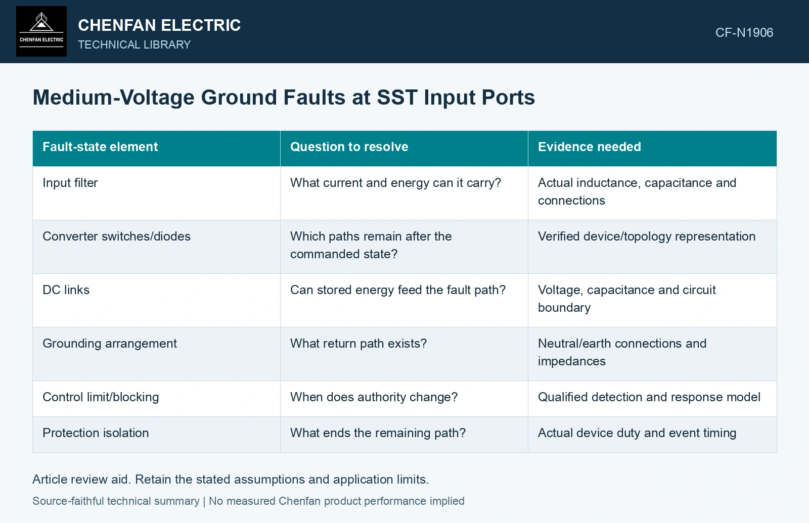
Map the paths in each control state
| Fault-state element | Question to resolve | Evidence needed |
|---|---|---|
| Input filter | What current and energy can it carry? | Actual inductance, capacitance and connections |
| Converter switches/diodes | Which paths remain after the commanded state? | Verified device/topology representation |
| DC links | Can stored energy feed the fault path? | Voltage, capacitance and circuit boundary |
| Grounding arrangement | What return path exists? | Neutral/earth connections and impedances |
| Control limit/blocking | When does authority change? | Qualified detection and response model |
| Protection isolation | What ends the remaining path? | Actual device duty and event timing |
The matrix should include valid operating states and credible failures. A normal current-control model does not necessarily remain valid during an earth fault.
Separate controlled current from physical conduction
A controller may limit its commanded current only within its available voltage and hardware domain. Diode conduction, charged capacitors or failed switches can create another contribution. A zero current reference is not proof that the fault current is zero.
Ground potential and port insulation need their own assessment. Current limitation does not remove all voltage stress. If a topology floats a link or changes its common-mode state during blocking, preserve that boundary in the model.
Use sequence quantities with their limits
Sequence components can still organize measured or calculated three-phase quantities. The limitation concerns assuming a fixed linear equivalent for a nonlinear, state-changing converter. State the domain in which a sequence model is valid and what replaces it outside that domain.
Kenyon et al.’s generic PSCAD study distinguishes current-limited response and momentary cessation in a grid-following inverter model [1]. It does not establish the selected SST’s ground-fault waveform. Reconstruct the actual SST topology [2], grounding and passive paths, then validate its state-changing model against the site protection and insulation duties.
Verify the event trajectory
The evidence should show fault inception, control response, remaining conduction and eventual isolation. Check current, energy and relevant voltage across the complete interval. A simulation that begins with all switches blocked can omit the detection interval and its duty.
The resulting model gives protection engineers a physical account of what the input port contributes and what can terminate that contribution. That account is more useful than assigning an SST the sequence impedance of a conventional transformer solely because both connect the same MV and LV voltage levels.
References
- R. W. Kenyon, A. Sajadi, A. Hoke and B.-M. Hodge, Open-Source PSCAD Grid-Following and Grid-Forming Inverters and a Benchmark for Zero-Inertia Power System Simulations, NREL/CP-5D00-78402, April 2021.
- D.-M. Predescu and Ș.-G. Roșu, Solid State Transformers: A Review—Part I: Stages of Conversion and Topologies, Technologies 13, 74, 2025. DOI: 10.3390/technologies13020074.