

A modular SST has a spare cell. That does not prove it can continue through every cell failure. The failed circuit must be detected and contained, the bypass path must support the duty, and the remaining cells must stay within their voltage, current and thermal limits. [1]
Assess bypass by fault type and by the electrical path left afterward. A control shutdown is not the same as physical isolation of a failed semiconductor or capacitor.
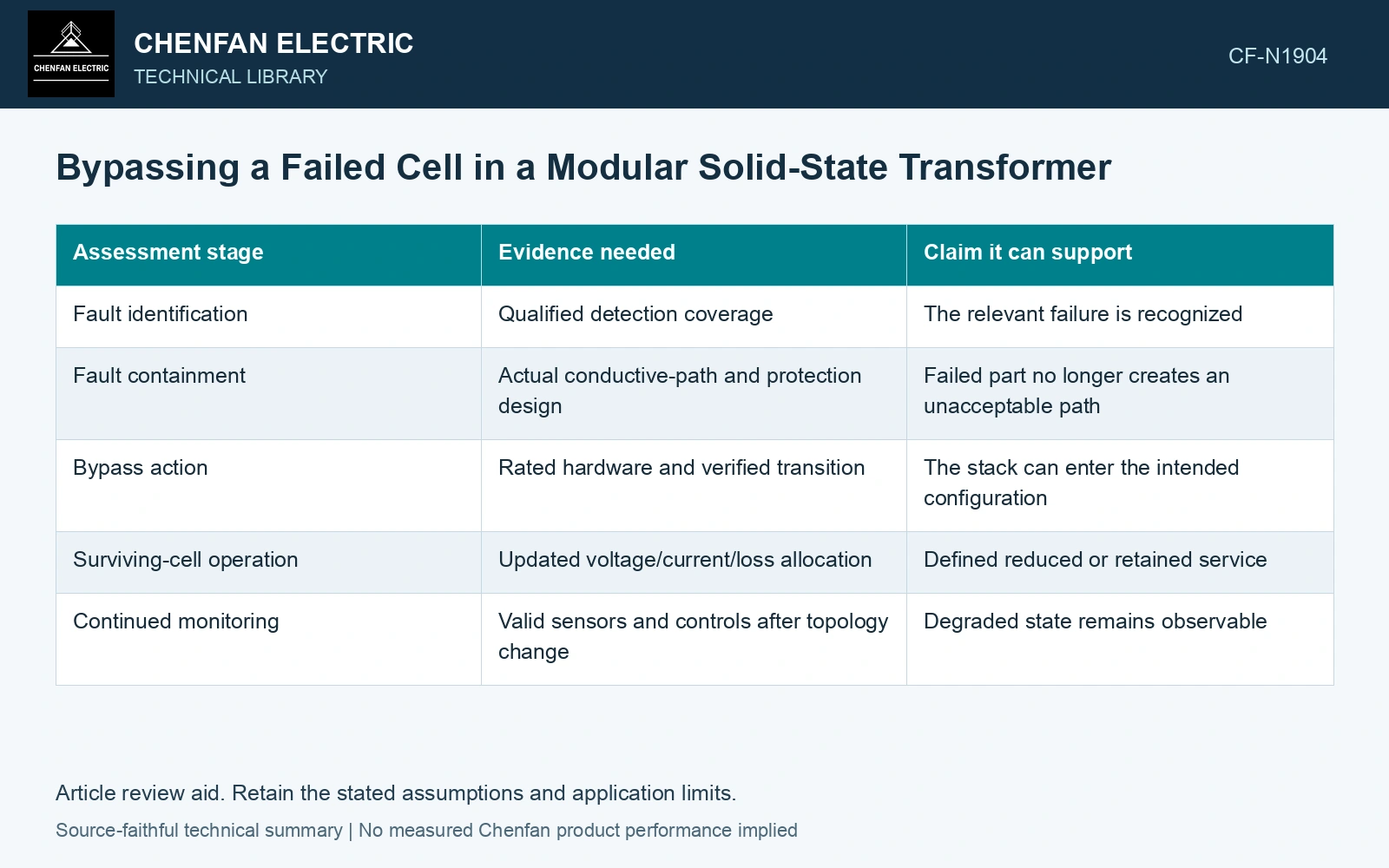
Separate containment from remaining capability
| Assessment stage | Evidence needed | Claim it can support |
|---|---|---|
| Fault identification | Qualified detection coverage | The relevant failure is recognized |
| Fault containment | Actual conductive-path and protection design | Failed part no longer creates an unacceptable path |
| Bypass action | Rated hardware and verified transition | The stack can enter the intended configuration |
| Surviving-cell operation | Updated voltage/current/loss allocation | Defined reduced or retained service |
| Continued monitoring | Valid sensors and controls after topology change | Degraded state remains observable |
A spare count supplies none of these results by itself. Different faults can leave different paths and require different dispositions.
Recalculate the stack allocation
For an illustrative equal-voltage series stack of n active cells carrying total voltage V, each sees V/n. If one is removed and V is unchanged, equal sharing among n − 1 cells gives V/(n − 1). This arithmetic assumes compatible cells and successful redistribution. It does not establish their permitted voltage.
If the surviving cells cannot accept that increase, the operating envelope must change or service must cease according to the approved design. Output current sharing and cooling limits also need recalculation; voltage arithmetic alone cannot establish remaining power.
Include the transition energy
Stored energy and inductor current can persist when the topology changes. The bypass device and protection must handle the actual transition, not merely the eventual steady state. A simulation that begins after the failed cell has disappeared can miss the most demanding interval.
Huber and Kolar describe redundant converter cells as a reliability mechanism. For an electrical bypass event, verify remaining-cell voltage, current, modulation and thermal demand separately; a redundancy count does not establish containment or uninterrupted rated operation. [2]
State the supported degraded state
The qualification record should name covered fault types, transition conditions, surviving module limits and the allowed service envelope. Include any limitation on duration, reactive support or other ports where the design requires it.
Assume ten identical active series cells support 10 kV equally, so each carries 1.0 kV. Bypassing one at unchanged total voltage raises the other nine to 1.111 kV each, an 11.11% increase. If an assumed permitted continuous cell voltage is 1.05 kV, the post-bypass stack must be limited to at most 9 × 1.05 = 9.45 kV under this ideal equal-sharing screen. Verify transient redistribution, modulation and isolation limits before authorising the degraded mode; successful bypass switching alone does not establish continued rated operation.
A customer can then distinguish verified continued operation from a repair-oriented spare-module strategy. Both can be useful. The technical decision depends on the path the hardware can safely establish and the duty the remaining modules can support, rather than the reassuring presence of one extra cell.
References
- D.-M. Predescu and Ș.-G. Roșu, Solid State Transformers: A Review—Part I: Stages of Conversion and Topologies, Technologies 13, 74, 2025. DOI: 10.3390/technologies13020074.
- J. E. Huber and J. W. Kolar, Solid-State Transformers: On the Origins and Evolution of Key Concepts, IEEE Industrial Electronics Magazine 10(3), 2016. DOI: 10.1109/MIE.2016.2588878.