

A shell-form end pancake can couple to the adjacent coil group, core, tank, lead and insulation structure. Those neighbors differ between the line end and the grounded end. Treating both ends as copies of one uniform internal section can miss their local transient duty.
Define the applied waveform and the actual terminal connections first. Then build a network that preserves the end pancake’s internal turn or section divisions where those divisions affect the voltage of interest.
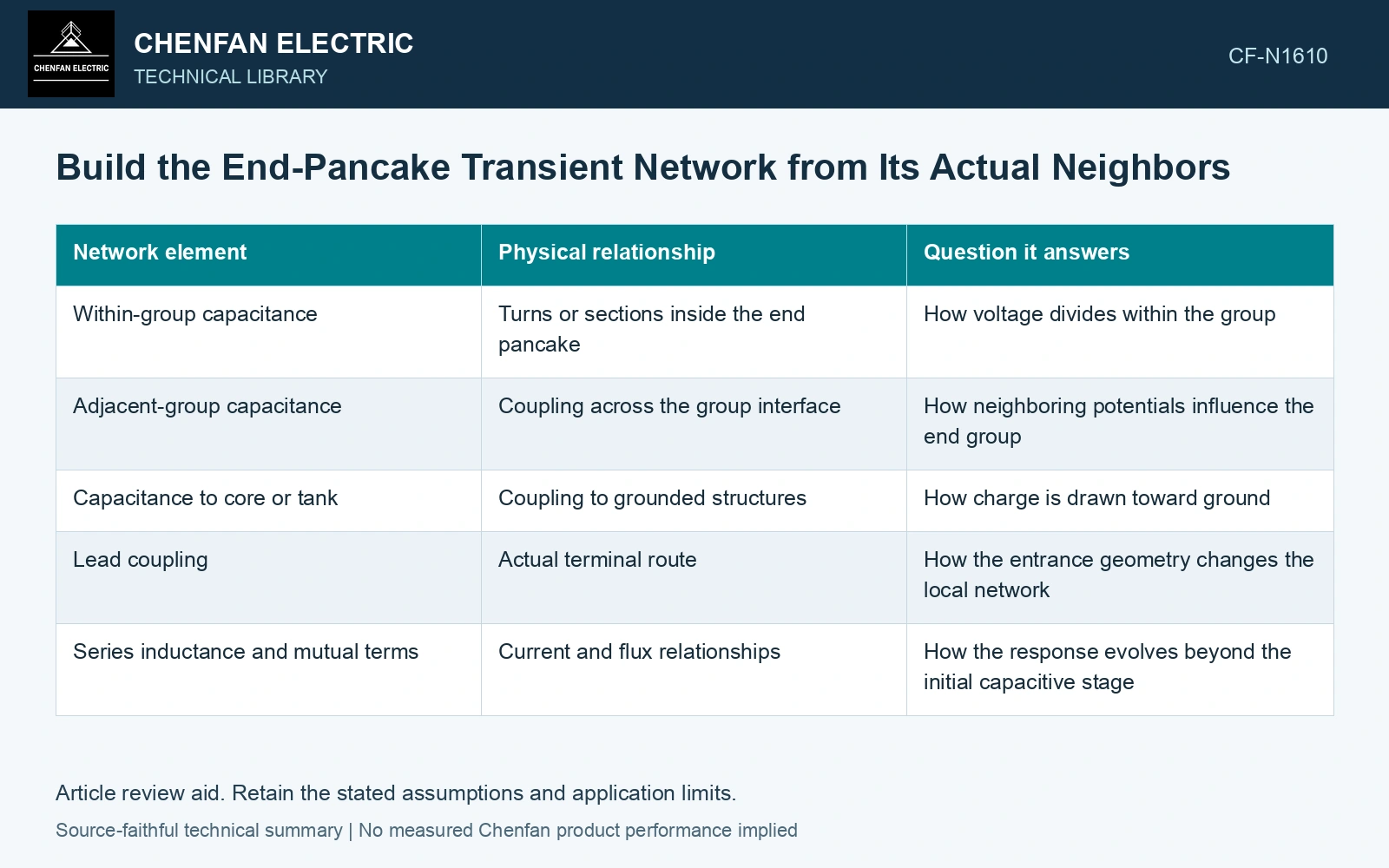
Separate the capacitance paths
| Network element | Physical relationship | Question it answers |
|---|---|---|
| Within-group capacitance | Turns or sections inside the end pancake | How voltage divides within the group |
| Adjacent-group capacitance | Coupling across the group interface | How neighboring potentials influence the end group |
| Capacitance to core or tank | Coupling to grounded structures | How charge is drawn toward ground |
| Lead coupling | Actual terminal route | How the entrance geometry changes the local network |
| Series inductance and mutual terms | Current and flux relationships | How the response evolves beyond the initial capacitive stage |
At an idealized initial instant dominated by capacitance, node voltages follow charge relationships and boundary conditions. Equal physical group count does not impose equal voltage division. Later behavior depends on inductance, resistance, coupling and the waveform’s frequency content.
Compare the two ends explicitly
Extract the line-end and grounded-end parameters from their actual geometry using an appropriate method. Keep the parameter definitions and units consistent. A capacitance matrix should preserve its reference and conductor ordering; moving entries between differently defined networks can create an apparently plausible but incorrect model.
Calculate both group-to-group voltage and within-group voltage. A modest voltage across the entire end pancake can coexist with a concentrated internal distribution. Conversely, a large group potential to ground does not tell the voltage across every adjacent turn.
Check the effect of nearby grounded metal, lead position and barrier arrangement within realistic geometric bounds. These changes can alter local coupling without materially changing the winding’s nominal turns.
Test model resolution against the requested output
Subdivide the end region until the voltage quantities relevant to the decision stabilize within the model’s capability. One lumped node cannot describe an internal voltage gradient. Excessive subdivision with unverified parameters can also create false detail.
Compare predicted terminal or accessible internal response with representative transient evidence where qualified measurements exist. Agreement in one terminal waveform does not uniquely validate all buried node voltages.
Use the network to identify the end-region interfaces that deserve detailed field assessment and design qualification. It is a bridge from the actual connection and geometry to a local voltage duty, not a substitute for dielectric evidence or a reason to assign every pancake an equal fraction of terminal stress. Assess the relevant measured quantities with a defined measurement model and propagated uncertainty [1].
Resolve the initial end-node voltage from charge balance
Assume an initially uncharged, purely capacitive screening network: an end node has 100 pF to a 100 kV step terminal and 300 pF to ground, with other couplings omitted. Charge balance gives Vnode = 100/(100 + 300)×100 = 25 kV. The first interface then sees 75 kV. If assumed ground capacitance falls to 100 pF, node voltage becomes 50 kV and first-interface voltage becomes 50 kV. The original interface duty is 50% higher. Use actual neighboring capacitances to select the detailed end-region dielectric review; these ideal step values do not replace a time-domain impulse model. Record rated quantities and test conditions on the general power-transformer basis of IEC 60076-1 [2].
References
- JCGM, JCGM 100:2008, Evaluation of measurement data — Guide to the expression of uncertainty in measurement, 2008.
- IEC, IEC 60076-1:2011, Power transformers – Part 1: General.