

Rectifier commutation transfers current between conductor paths. Its inductive voltage depends on the loop formed by those paths and their return connections. Matching their lengths does not guarantee matching loop inductance because spacing and mutual coupling also matter. IEC 61378-1 covers industrial converter-transformer specification, design and testing [1].
Model the bus arrangement with all relevant current paths. Use one coordinate and reference convention for the inductance matrix. A matrix extracted for isolated open conductors is not directly comparable with one describing complete loops without a consistent mapping.
Form the actual transfer loop
For a linear inductance matrix L and conductor-current vector i, magnetic energy is W = ½iᵀLi under the model’s assumptions. If a commutation current coordinate q produces i = aq, its effective inductance is Lcomm = aᵀLa.
For a simple two-conductor transfer with a = (1, −1), Lcomm = L11 + L22 − 2L12 when the mutual matrix is symmetric and references are consistent. The minus sign follows the opposed current directions; it is not a rule to apply to every bus pair regardless of reference arrows.
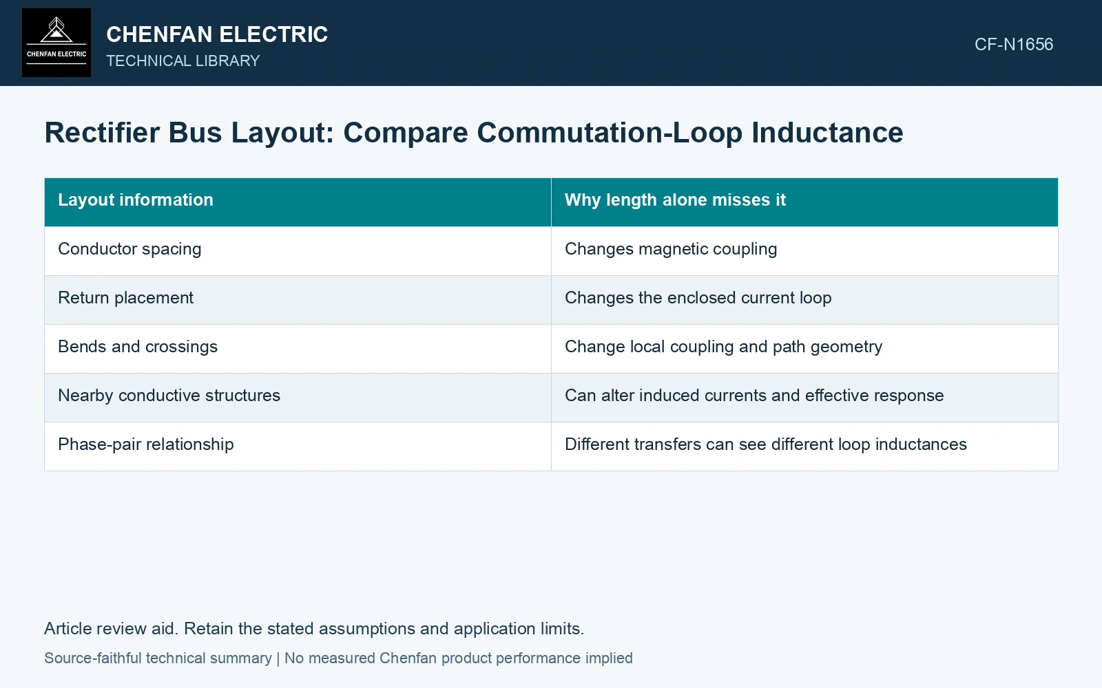
| Layout information | Why length alone misses it |
|---|---|
| Conductor spacing | Changes magnetic coupling |
| Return placement | Changes the enclosed current loop |
| Bends and crossings | Change local coupling and path geometry |
| Nearby conductive structures | Can alter induced currents and effective response |
| Phase-pair relationship | Different transfers can see different loop inductances |
Compare each commutation pair
Calculate the loop coordinate for each relevant phase-to-phase transfer. Keep its source and device path consistent. A symmetric-looking bus can still have different return paths or neighboring metal on one phase.
Use the matrix to predict inductive voltage during the actual current-transfer waveform, not merely to produce a scalar layout ranking. Frequency-dependent conductor behavior may require an expanded impedance model when switching details matter.
Compare compact and separated layouts under equivalent electrical and insulation constraints. Bringing paths closer can change coupling, but clearance, thermal and mechanical requirements still govern what arrangement is feasible.
Compare mutual coupling for the complete transfer loop
Assume a symmetric linear two-conductor matrix with L11 = L22 = 2 µH. For opposed reference currents, mutual terms of 1.5 µH and 0.5 µH give loop inductances 2 + 2 − 2 × 1.5 = 1 µH and 3 µH. At an assumed transfer rate 1 kA/ms, inductive voltages are 1 V and 3 V. With a 10 kA loop coordinate, stored energies are 50 J and 150 J. Prefer no layout from length alone: compare these loop quantities while retaining insulation and thermal constraints.
Validate the extracted relationship
Use an independent calculation or qualified measurement suited to the loop and frequency range. Test the complete path rather than measuring one conductor in isolation and adding its result to another.
Check matrix symmetry, reference directions and energy consistency where the model requires them. Unexpected negative loop energy can indicate an inconsistent extraction or mapping rather than a beneficial physical design.
A layout comparison needs the impedance of each actual commutation loop, with its reference arrows and return connections. If equal-length buses give unequal loop impedances, compare spacing, crossings and adjacent metal before assigning the imbalance to a winding.
Retain an explicit measurement model and input uncertainties when comparing measured and calculated duty [2].
References
- IEC, IEC 61378-1:2011, Converter transformers – Part 1: Transformers for industrial applications.
- JCGM, JCGM 100:2008, Evaluation of measurement data — Guide to the expression of uncertainty in measurement, 2008.