

A railway traction transformer supplying single-phase loads must be assessed for its effect on the three-phase source. Average traction megawatts cannot describe phase imbalance, section loading or the influence of train movement. The specification should use the approved traction connection, time-varying load patterns and grid-study requirements rather than treating the load as automatically balanced three-phase demand.
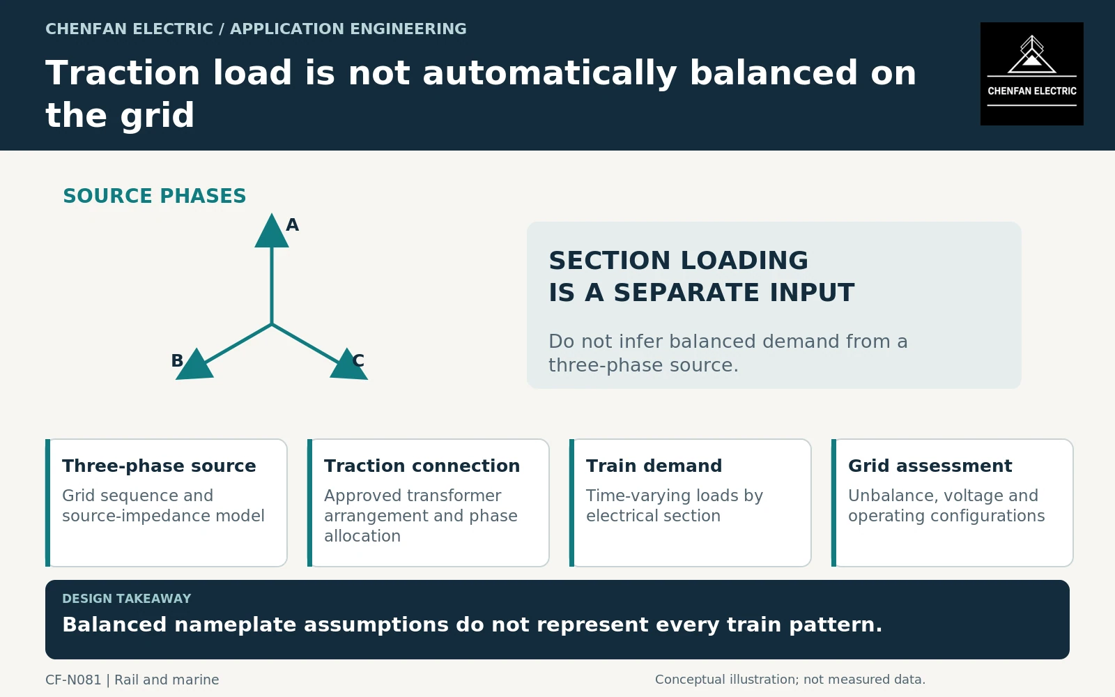
Identify the traction supply architecture
Show the source network, traction transformer arrangement, electrical sections and any relevant return or auxiliary systems at the level needed by the study. State which quantities are referenced to the grid side and which belong to the traction side.
IEC 62695 addresses transformers for fixed railway installations, including defined traction and auxiliary applications. It provides an equipment framework, not the train timetable or network-unbalance assessment for a specific railway. [1]
Different connection arrangements can distribute single-phase duties differently. The project should supply the approved scheme rather than asking the transformer supplier to infer it from the word traction.
For example, a Scott arrangement relates a three-phase source to two outputs in quadrature in its ideal representation. Its balanced-input condition depends on the two-output loading relationship; unequal magnitudes or power factors must be represented in the study. A Scott connection should not be specified as a promise of balanced grid current in every traction state.
Preserve section-level demand
Train acceleration, coasting, braking and location can produce different electrical demands in each section. Several sections may be loaded unequally, and regeneration can change power direction where the system permits it.
The study should identify whether its load data come from measured operation, timetable simulation or design scenarios. A daily energy figure is not a substitute for coincident section loads and their phase relationships.
General transformer application guidance addresses connections, loading and voltage behavior. It should be applied with the actual railway architecture rather than used to assume balanced operation. [2]
A useful scenario set includes a heavily loaded section, unequal loading of adjacent sections, relevant feeder outages and permitted regenerative states. Do not assume that a favorable average phase allocation holds during every operational interval.
Separate transformer duty from grid acceptance
The transformer supplier needs winding currents, voltages, durations and connection information. The grid study needs suitable source impedance, phase allocation and time-varying loading to assess voltage and unbalance at the agreed boundary.
| Evidence | Question it answers |
|---|---|
| Winding duty schedule | Can the equipment support the stated loading? |
| Connection and impedance model | How does the transformer participate in the network? |
| Section load scenarios | Which railway states are represented? |
| Grid-unbalance study | What occurs at the specified source boundary? |
| Protection review | How are actual source and fault states coordinated? |
A transformer type test does not establish the railway’s grid-unbalance performance. Likewise, an acceptable network calculation does not replace the equipment’s specified thermal and dielectric evidence.
Freeze the operating cases, not a generic railway label
The enquiry should reference the traction single-line diagram, phase allocation, section-duty scenarios and applicable equipment specification. Include any future service pattern or network extension that the transformer must support.
If an operating restriction is needed to remain within the assessed envelope, state it explicitly and identify how it is enforced. A timetable or section configuration change can alter the electrical duty even when annual energy consumption is similar.
The final acceptance record should reconcile transformer data with the network model and approved operating scenarios. That provides a defensible statement of suitability for the specified railway duty without implying that every single-phase traction load behaves like a balanced industrial three-phase load.
Core procurement checkpoint: Do not infer traction-core geometry from the grid label
A single-phase traction supply connected to a three-phase grid requires a defined equipment arrangement. The core supplier needs the approved geometry and quantities for that arrangement, not merely the grid voltage or railway project capacity. Manufacturing acceptance of the core should remain separate from traction-load unbalance, network compatibility and the complete transformer’s electrical and mechanical qualification.
For the core enquiry: Approved traction-transformer core drawing; limb/window arrangement; material specification; quantity by design; complete-equipment qualification boundary.