

Paired saturable reactors can arrange control windings so that induced AC voltages oppose. The cancellation depends on winding polarity, turns and the two cores’ flux histories. A schematic opposition symbol does not prove zero AC voltage at the control terminals. [1]
Draw both magnetic cores, AC windings and control-winding connections. Mark winding dots and current directions. For each control winding, induced voltage follows ek = NkdΦk/dt with its connection sign. Flux is in webers, turns are dimensionless, t is in seconds and voltage is in volts.
Calculate the residual rather than assuming cancellation
For an opposed pair, eres = N1dΦ1/dt − N2dΦ2/dt under the stated polarities. Equal turns and equal flux derivatives cancel ideally. Different saturation timing or flux amplitude leaves a residual.
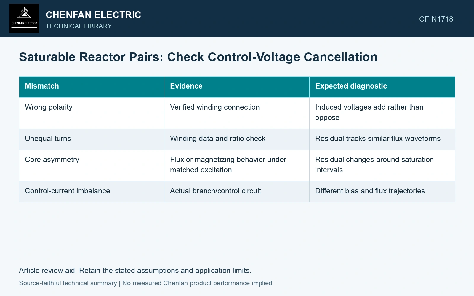
| Mismatch | Evidence | Expected diagnostic |
|---|---|---|
| Wrong polarity | Verified winding connection | Induced voltages add rather than oppose |
| Unequal turns | Winding data and ratio check | Residual tracks similar flux waveforms |
| Core asymmetry | Flux or magnetizing behavior under matched excitation | Residual changes around saturation intervals |
| Control-current imbalance | Actual branch/control circuit | Different bias and flux trajectories |
Apply Faraday’s law with the actual connection signs to the simultaneous flux histories. Opposed voltage labels establish a subtraction, not equality of the two waveforms. [2]
Calculate the residual control-winding voltage
Assumptions: each opposed control winding has 100 turns; at 50 Hz their flux derivatives are 0.010 cos(2π50t) and 0.009 cos(2π50t) Wb/s. Voltages are 1.0 and 0.9 V peak, leaving 0.10 V peak or 0.0707 V RMS. Against an assumed 0.05 V peak residual allowance, cancellation fails by 0.05 V. Reversed polarity would add the voltages to 1.90 V peak, 19 times the opposed residual. Hold the cancellation claim and verify polarity, core trajectories and control-circuit loading. [2]
Include the control circuit response
The residual voltage drives whatever impedance and filtering the control circuit presents. Record its source, protection and insulation boundaries. A low RMS residual can still contain a short peak relevant to a component; retain the waveform as well as its averaged value.
References
- K. E. Glading, Navy Electricity and Electronics Training Series, Module 8—Introduction to Amplifiers, NAVEDTRA 14180, Naval Education and Training Professional Development and Technology Center, September 1998, chapter 3, Saturable-Core Reactor.
- U.S. Department of Energy, DOE-HDBK-1011/4-92, Electrical Science, Volume 4, 1992.