

An NGR monitor may be correctly rated at one input and still leave another assembly interface unresolved. During an earth fault, the transformer neutral and its connected sensing components can rise in potential relative to ground. The complete path of that voltage needs an insulation and protection assessment. [1]
The monitor’s data sheet is one part of the record. Coupling components, wiring, mounting, control supply and enclosure clearances can have different boundaries and duties.
Split the assembly into voltage domains
Identify the neutral-side sensing domain, any intermediate coupling domain and the low-voltage control domain. Mark deliberate bonds and isolation barriers. The diagram should make it possible to see where fault voltage appears, not simply show a box labeled monitor connected to a ground symbol.
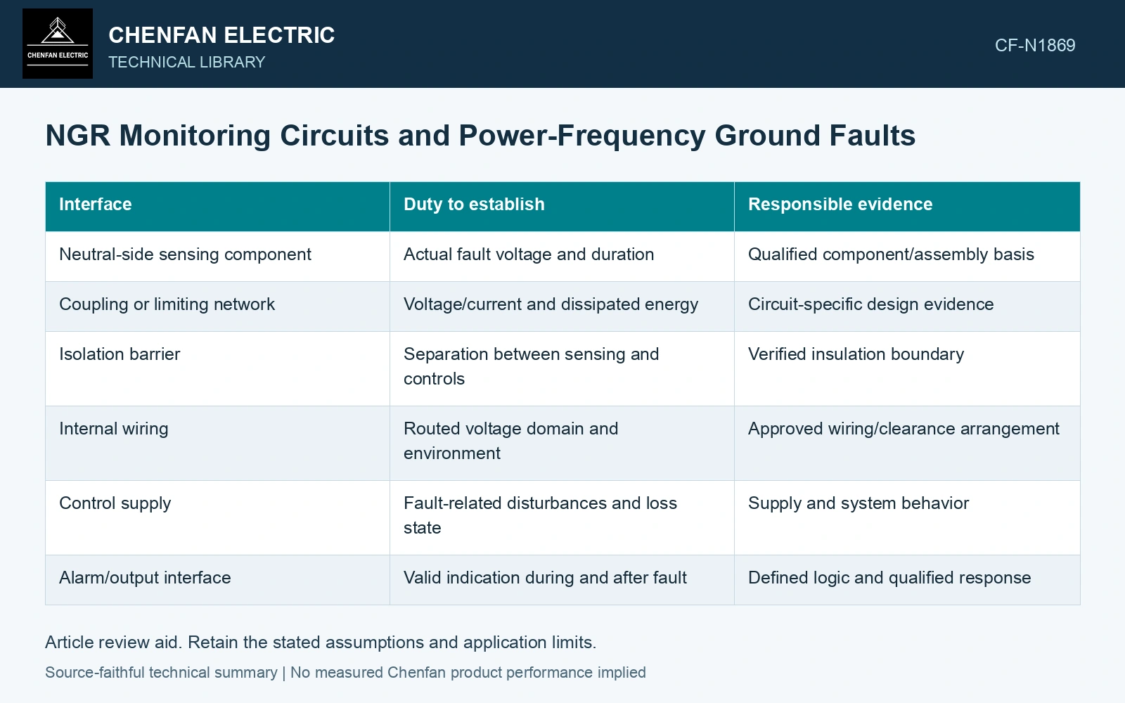
| Interface | Duty to establish | Responsible evidence |
|---|---|---|
| Neutral-side sensing component | Actual fault voltage and duration | Qualified component/assembly basis |
| Coupling or limiting network | Voltage/current and dissipated energy | Circuit-specific design evidence |
| Isolation barrier | Separation between sensing and controls | Verified insulation boundary |
| Internal wiring | Routed voltage domain and environment | Approved wiring/clearance arrangement |
| Control supply | Fault-related disturbances and loss state | Supply and system behavior |
| Alarm/output interface | Valid indication during and after fault | Defined logic and qualified response |
Keep power-frequency and transient duties visible
A power-frequency fault voltage can persist through the clearing interval. A transient surge is another duty with a different waveform. A component qualified for one is not automatically qualified for the other. Preserve the actual ratings and test conditions used in each comparison.
Energy in a sensing or limiting component also matters. A voltage rating alone cannot establish its thermal ability to sustain the connected duty. Where the monitor intentionally stops supervising during the fault, the system needs a defined handling of that state rather than silently treating the last healthy indication as current evidence.
Check failure consequences
Consider open sensing components, lost monitor supply, failed isolation and incorrect output status in the approved design review. The issue is not only whether the monitor survives; it is whether its failure changes the grounding path or gives misleading information.
Capacitive reactance changes inversely with frequency. [2] Use the sensing network’s actual impedance at its injected frequency and at power frequency; continuity of one signal path cannot establish the other path’s fault-duty performance.
Separate the monitoring and fault frequencies
Assume a monitor evaluates continuity at 10 kHz while the fault assessment concerns 50 Hz. A capacitive bypass of 1 nF has reactance about 15.9 kΩ at the monitoring frequency and 3.18 MΩ at 50 Hz. A monitoring signal may therefore follow a path that carries negligible fault-frequency current. Verify the specific sensing network.
References
- IEEE, IEEE C57.32-2015, IEEE Standard for Requirements, Terminology, and Test Procedures for Neutral Grounding Devices (historical edition).
- U.S. Department of Energy, DOE-HDBK-1011/3-92, Electrical Science, Volume 3, June 1992.