

Moving a primary bar closer to the inside of a CT core does not create another primary turn. The same conductor still links the core. The concern is how the real conductor route, return path and surrounding metal redistribute local field and heat around a multi-core assembly. [1] [2]
This distinction prevents a common modelling error: applying a simple inverse-distance field value to one point and treating it as the CT’s whole-core flux or ratio. A toroidal magnetic circuit and its secondary winding respond to the complete linked-current geometry.
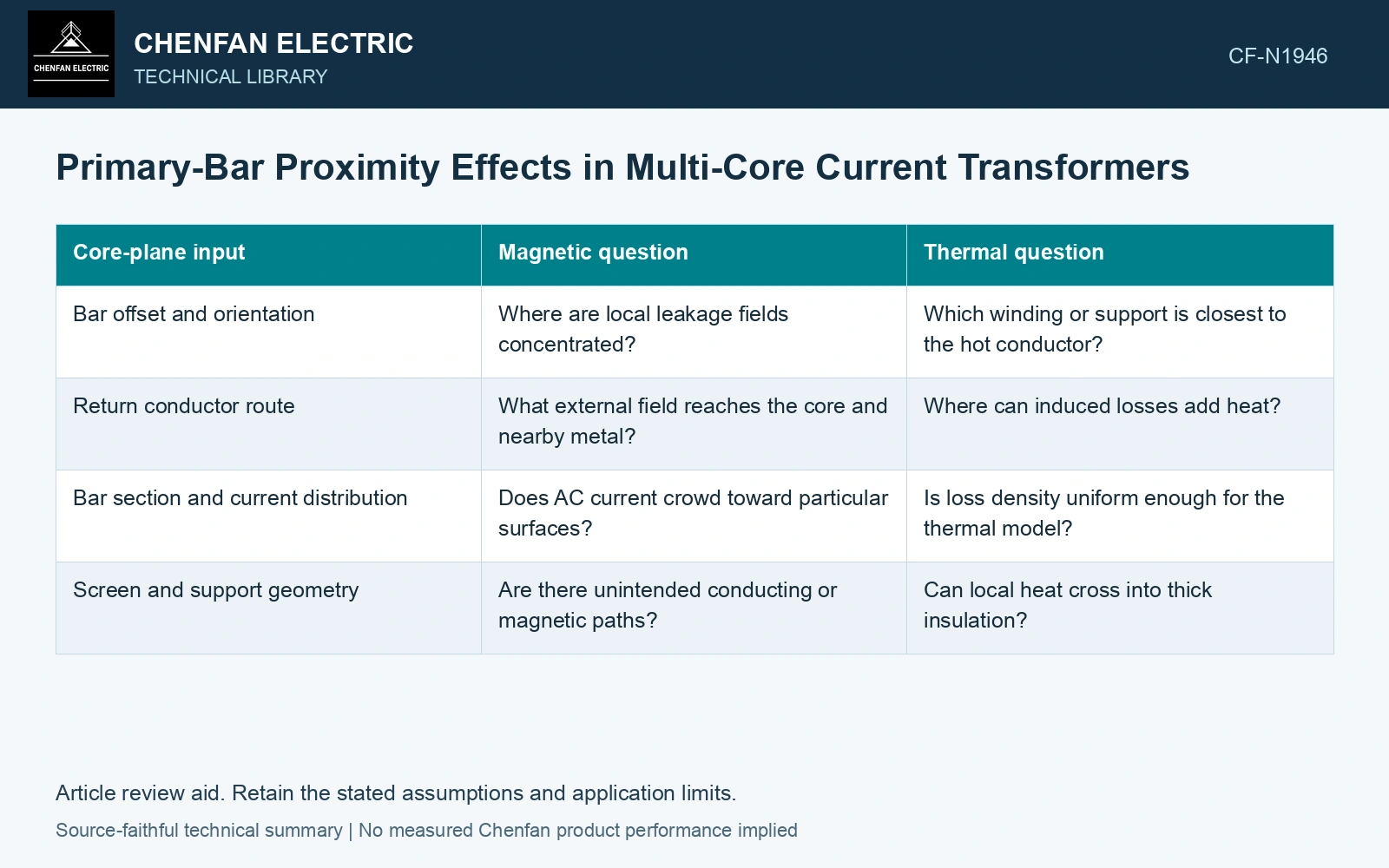
Record the position at each core plane
A straight bar can have a consistent offset. A bent or stepped conductor can pass through different locations in successive core windows. Measure or model the actual route at each core rather than giving the stack one centring dimension.
| Core-plane input | Magnetic question | Thermal question |
|---|---|---|
| Bar offset and orientation | Where are local leakage fields concentrated? | Which winding or support is closest to the hot conductor? |
| Return conductor route | What external field reaches the core and nearby metal? | Where can induced losses add heat? |
| Bar section and current distribution | Does AC current crowd toward particular surfaces? | Is loss density uniform enough for the thermal model? |
| Screen and support geometry | Are there unintended conducting or magnetic paths? | Can local heat cross into thick insulation? |
Keep the linked-current model and local model separate
For an ideal closed core, the primary ampere-turn linkage depends on the enclosed current and turn count. Real cores have finite permeability, joints, gaps and nonuniform geometry. Nearby conductors can create leakage fields or local magnetization patterns that the ideal model omits.
A useful detailed model should reproduce the overall winding response while also resolving regions near the bar, gaps and metal screens. A colourful local field plot without a linked-flux or secondary-output check cannot establish CT accuracy. Conversely, an acceptable overall ratio measurement does not show that every local region has an acceptable thermal state.
Follow the heat independently
Primary conductor heating depends on current and effective AC resistance, including joints and the influence of frequency and surrounding conductors. The heat then crosses oil, insulation or structural contacts before reaching a core or winding. Proximity affects this path even if the conductor loss itself is unchanged.
Compare temperatures at identified core and insulation regions under the same load and cooling boundary. A head or tank temperature may average over the local difference being investigated. If the conductor route is changed to improve spacing, re-evaluate supports and lead routes as well; the mechanical change can move another thermal or dielectric boundary.
Use catalogue gauge 0.23 mm [3]. Assume 200 net-steel layers at 20 mm width: section is 920 mm². In two assumed test states with the same linked-flux amplitude 0.800 V·s and 500-turn winding, mean core B = ψ/(NA) = 1.739 T in both. Separately, an isolated straight 1,000 A RMS bar gives free-air field 2/4 mT at distances 0.10/0.05 m. An assumed local linear eddy-loss indicator ∝B² increases fourfold; neither that field nor its loss ratio is the whole toroidal-core induction or CT ratio. Reject such substitution and resolve actual bar/return geometry with winding output and local heating checks.
A position review should end with two separate conclusions: whether the CT’s electrical response is supported, and whether the altered local field and heat distribution are acceptable. One result cannot silently stand in for the other.
References
- ABB, Instrument Transformers Application Guide, publication 1HSM 9543 40-00en, Edition 4, February 2015, sections 3.4 and 4.9–4.12.
- B. Dong et al., Three-Dimensional Electro-Thermal Analysis of a New Type Current Transformer Design for Power Distribution Networks, Energies 14, 1792, 2021. DOI: 10.3390/en14061792.
- Nippon Steel Corporation, Grain-Oriented Electrical Steel Sheets, catalogue D004je, April 2020, specification and typical-property tables.