

A gap-controlled CT core can leave core assembly with the right spacer position and reach coil completion in a different magnetic state. Winding tension, local pressing, handling fixtures and final clamps can transmit load into the gap region. A tidy coil exterior does not show whether that region moved. [1] [2]
ABB’s guide warns that the gap width of a gapped CT must remain constant. During winding, the practical task is to identify which process loads could change that width and to verify the assembled result. [1]
Follow the load into the joint
Draw the winding path around the core and mark where tension reacts against the core, insulation and fixture. Average tension is only one input. A crossover, local build-up or guide contact can introduce concentrated pressure near a gap, especially where winding support is uneven.
Separate temporary fixture loads from permanent coil restraint. A fixture may hold the joint open during winding; removing it can reveal movement that was hidden while the tool was installed. Final clamping can then introduce another change.
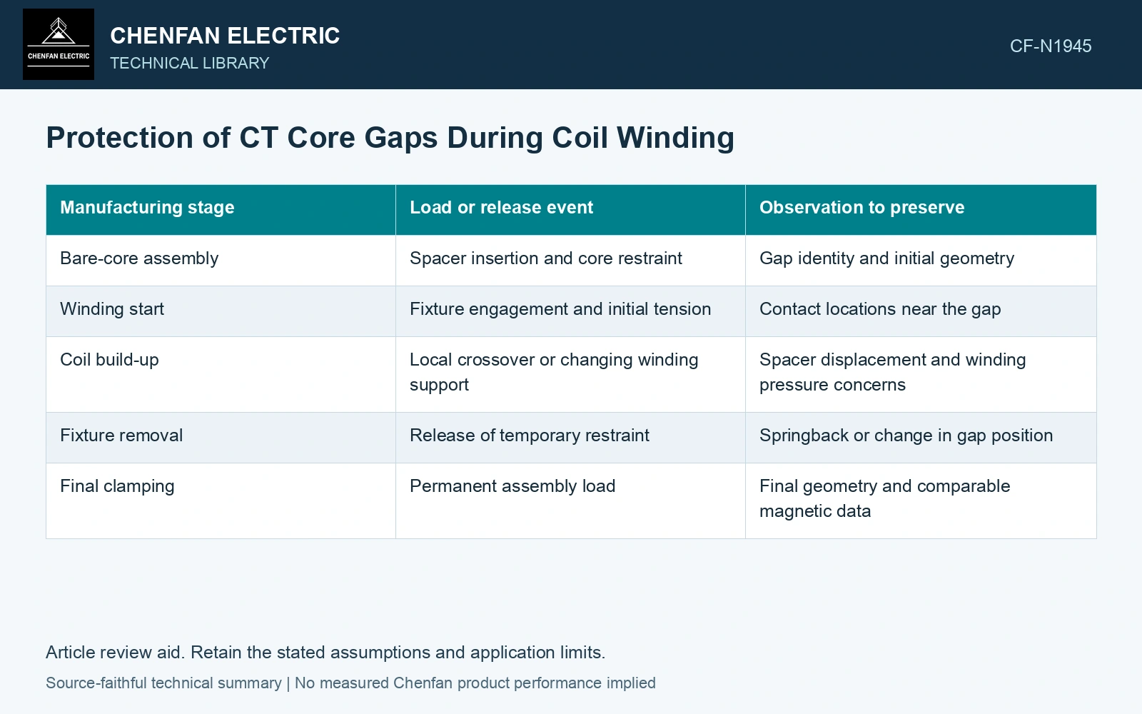
| Manufacturing stage | Load or release event | Observation to preserve |
|---|---|---|
| Bare-core assembly | Spacer insertion and core restraint | Gap identity and initial geometry |
| Winding start | Fixture engagement and initial tension | Contact locations near the gap |
| Coil build-up | Local crossover or changing winding support | Spacer displacement and winding pressure concerns |
| Fixture removal | Release of temporary restraint | Springback or change in gap position |
| Final clamping | Permanent assembly load | Final geometry and comparable magnetic data |
Do not let a spacer become an unnamed component
Retain the spacer’s identity, orientation and intended seating location. A replacement with the same visible thickness can have different compression or creep behaviour. Its compatibility with the insulation system also matters. These are process-design inputs; they cannot be settled by picking a generic hard sheet material.
Inspect the actual gap location by the approved manufacturing method. Avoid forcing a measurement tool into the gap in a way that changes the condition being assessed. Once winding hides the joint, earlier dimensional observations need a justified connection to the final assembly.
Compare magnetic measurements on equal terms
Compare excitation data before and after winding using consistent frequency, temperature, winding definition and magnetic history. A reduced gap generally lowers gap reluctance, but a changed excitation characteristic can also reflect turn count, connection errors, temperature or prior magnetization. Use the change to direct investigation rather than declaring a spacer failure from one curve.
Assume a GOES gap-controlled core uses catalogue 0.23 mm laminations, 200 layers and 20 mm strip width, giving nominal steel section 920 mm². [3] With an assumed total gap of 0.20 mm and negligible fringing, gap reluctance is 0.00020/(μ₀ × 0.000920) = 172,995 H⁻¹. If winding compression reduces the gap to 0.15 mm, this contribution falls by 25% to 129,746 H⁻¹. That change can shift excitation and reset behaviour. Recheck final gap geometry and comparable magnetic measurements after removing the winding fixture; the bare-core result no longer closes the changed construction.
Spacer identity, gap seating, local winding pressure and final restraint control this manufacturing risk. Do not infer the final gap from the coil’s external appearance or from temporary fixture dimensions.
If the final result differs, correlate it with the stage record: did the difference appear during coil build-up, fixture release or final clamping? That timing narrows the mechanical cause. The manufacturing control is effective when it preserves both the intended spacer geometry and the magnetic response after every load-transfer stage, instead of relying on a bare-core measurement that predates the winding.
References
- ABB, Instrument Transformers Application Guide, publication 1HSM 9543 40-00en, Edition 4, February 2015, sections 3.4 and 4.9–4.12.
- IEC, IEC 61869-2:2012, Instrument transformers — Part 2: Additional requirements for current transformers.
- Nippon Steel Corporation, Grain-Oriented Electrical Steel Sheets, catalogue D004je, April 2020, specification and typical-property tables.