

An AC-system phase jump changes the reference seen by an MMC control system. It is different from a pure voltage-magnitude dip, though the two can occur together. The converter’s transient current depends on its controls, stored energy and current limits as well as the transformer and network impedance. Apply the HVDC transformer specification framework of IEC/IEEE 60076-57-129 to the stated liquid-immersed equipment [1].
Define the disturbance at the transformer terminal plane: phase displacement, rise time, voltage magnitude and sequence content. Keep the same event clock for voltage, current, converter control states and DC quantities. A frequency estimator or phase-locked loop can filter the apparent phase change, so retain raw waveform evidence where available.
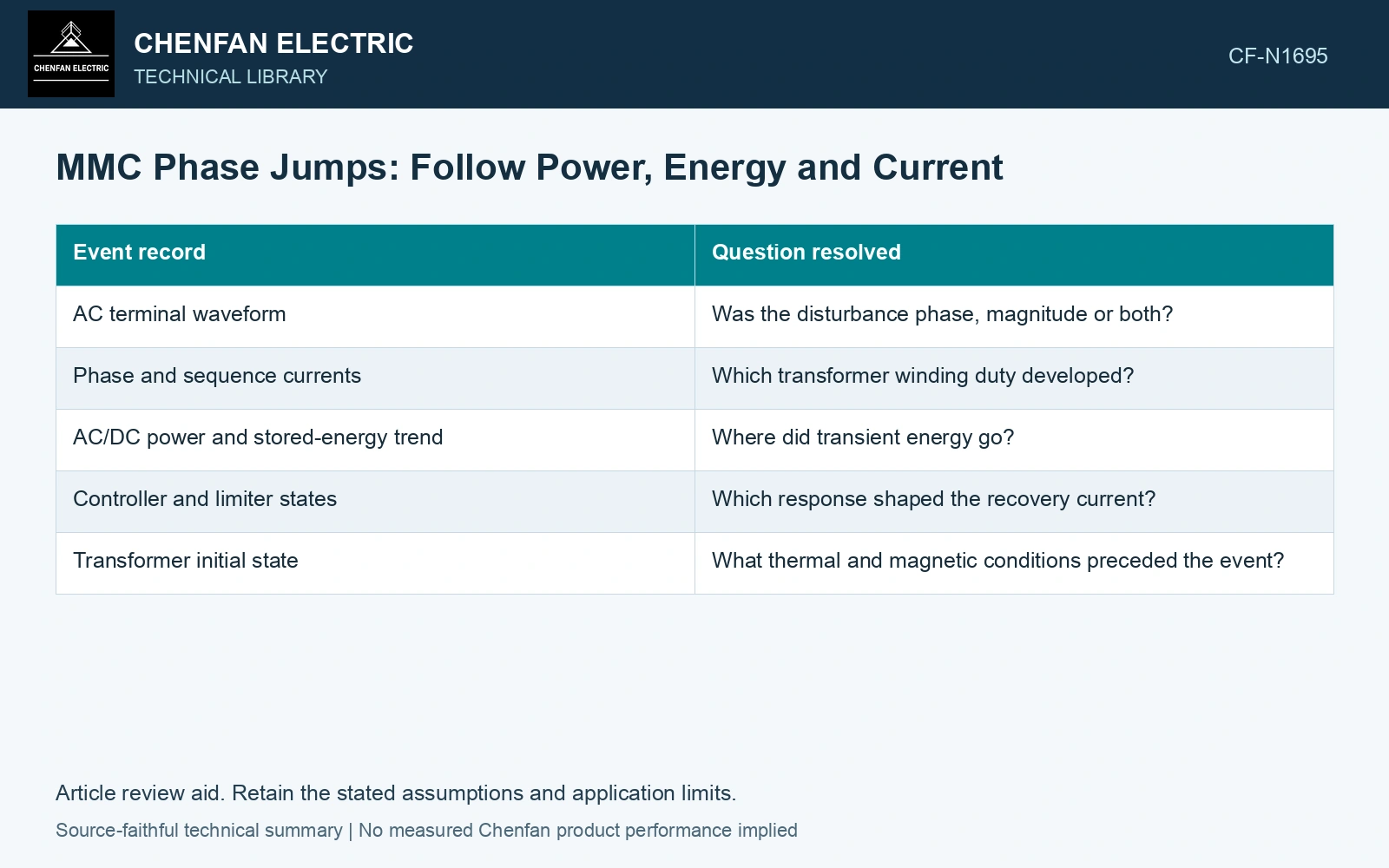
Use energy balance to check the event
At a consistent converter boundary, dE/dt = Pin − Pout − Ploss. Power is in watts, time in seconds and stored energy E in joules. Define the signs and include the storage actually inside the chosen boundary. A temporary mismatch between AC and DC power must appear as storage change or loss.
| Event record | Question resolved |
|---|---|
| AC terminal waveform | Was the disturbance phase, magnitude or both? |
| Phase and sequence currents | Which transformer winding duty developed? |
| AC/DC power and stored-energy trend | Where did transient energy go? |
| Controller and limiter states | Which response shaped the recovery current? |
| Transformer initial state | What thermal and magnetic conditions preceded the event? |
Reconcile a short power mismatch with stored energy
Assume an MMC boundary with AC power entering of 100 MW, DC power leaving of 80 MW and loss of 1 MW, held for 20 ms. Stored energy rises by (100 − 80 − 1) × 0.020 = 0.38 MJ. If initial capacitor energy is 10 MJ and capacitance remains fixed, the equivalent capacitor-voltage ratio is √(10.38/10) = 1.0188. This 1.88% rise checks the energy record; it does not specify transformer current. If simulated storage fails this balance, resolve boundary or sign errors before rating the recovery waveform.
A current limit is not a complete waveform
The converter’s advertised or configured current limit does not automatically specify instantaneous winding peaks. Sampling, control delays and the disturbance path matter. Use time-domain currents and their frequency content for transformer heating and force checks.
Compare a pure phase step with a magnitude dip and a combined case only when those cases belong to the station requirement. Preserve the same initial power and control mode so that the difference is interpretable.
The study should reconcile terminal power with storage change and show transformer current through the recovery period. If the energy balance fails, investigate sign conventions, boundaries or omitted storage before trusting the duty result. Do not substitute an LCC commutation-failure sequence for the MMC control response.
Use an EMT model that retains the MMC controls and connected network [2].
References
- IEC/IEEE, IEC/IEEE 60076-57-129:2017, Power transformers – Part 57-129: Transformers for HVDC applications.
- CIGRE WG B4.70, Guide for electromagnetic transient studies involving VSC converters, ELECTRA No. 316, June 2021, technical-brochure summary.