

A converter bushing can be qualified as a component while the installed transformer interface presents a different field geometry. The oil-end screen, adjacent leads, barrier position and tank connection belong to the installation. Component test evidence and installed-system evidence answer related but different questions. Apply the HVDC transformer specification framework of IEC/IEEE 60076-57-129 to the stated liquid-immersed equipment [1].
Identify the bushing’s specified voltage waveform and earth reference for the actual converter topology. State whether combined AC/DC stress applies and how the qualification defines preconditioning and history. Do not import an LCC bias into another topology without verifying the node potential.
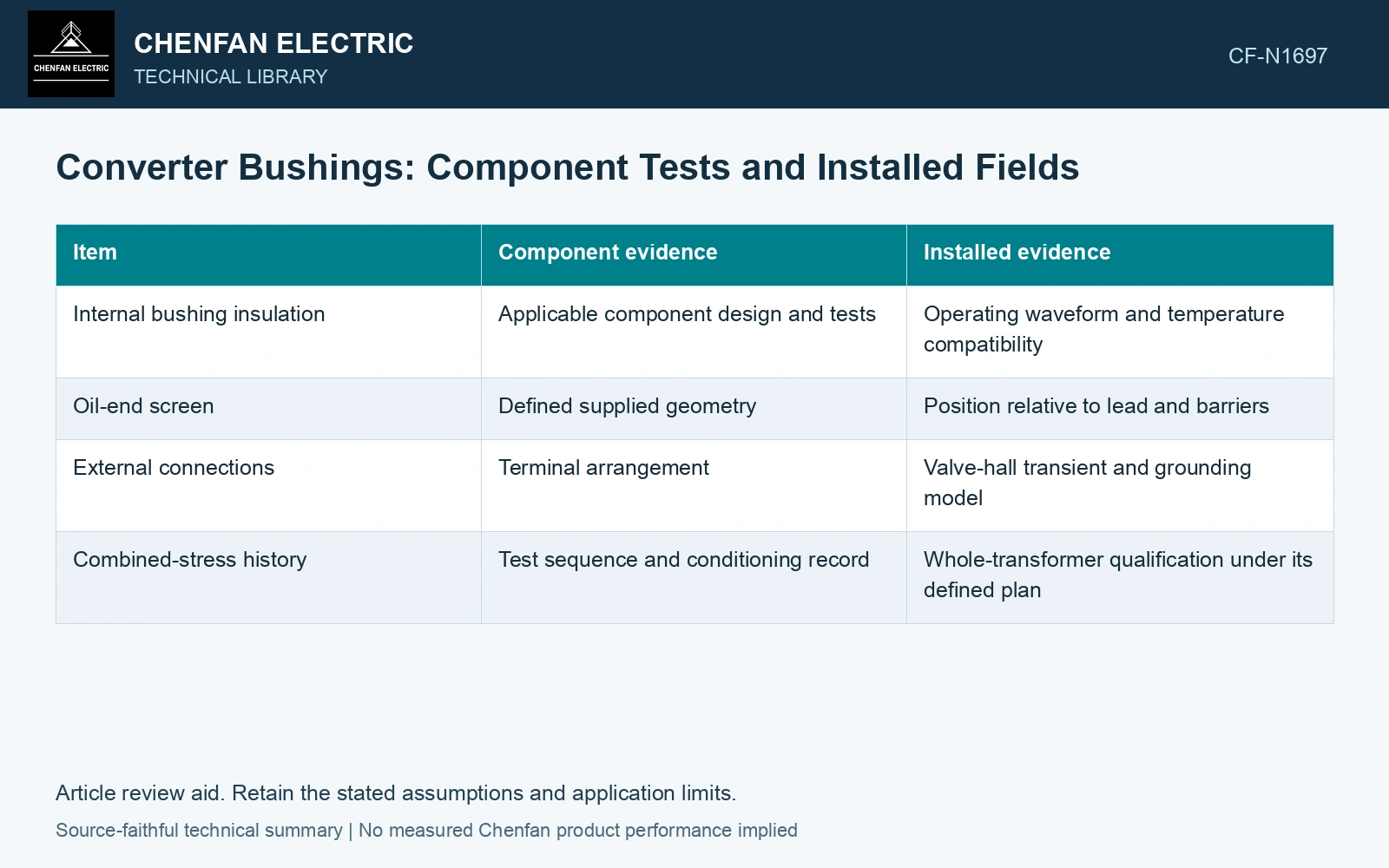
Split the evidence at the interface
| Item | Component evidence | Installed evidence |
|---|---|---|
| Internal bushing insulation | Applicable component design and tests | Operating waveform and temperature compatibility |
| Oil-end screen | Defined supplied geometry | Position relative to lead and barriers |
| External connections | Terminal arrangement | Valve-hall transient and grounding model |
| Combined-stress history | Test sequence and conditioning record | Whole-transformer qualification under its defined plan |
Compare the test fixture with the installation
Locate the earthed surfaces and grading screens in both configurations. A fixture may provide more open space or a different oil-end shield than the transformer. Identify those differences before claiming the component test reproduces the installed field.
Use the installed geometry to assess winding-to-bushing and bushing-to-tank paths. Include manufacturing tolerances that change screen overlap or edge clearances. Control the modeled screen and barrier positions during assembly.
Quantify the installation change before accepting the certificate
Assume the same applied crest of 200 kV across a component-fixture gap of 100 mm and an installed gap reduced to 80 mm. Uniform-field screening gives 2.0 and 2.5 kV/mm, a 25% increase. These are average fields, not local edge-field predictions. The numerical difference is sufficient to require the installed screen and barrier model before transferring component evidence. Keep the bushing certificate, installed geometry and combined-stress qualification as separate records.
Preserve combined-stress conditions
Record temperature, prior DC stress, polarity and interruption intervals where the qualification plan requires them. The public CIGRE TB406 summary emphasizes conductivity and polarization time, but its catalogue is not a substitute for the current applicable test requirements. [2]
Check which drawing, property and test covers each installed interface. A passed bushing test leaves an uncovered transformer-side field or voltage history unresolved. Obtain the missing interface evidence before treating component certificates as qualification of the complete assembly.
References
- IEC/IEEE, IEC/IEEE 60076-57-129:2017, Power transformers – Part 57-129: Transformers for HVDC applications.
- CIGRE JWG A2/B4.28, Technical Brochure 406, HVDC Converter Transformers – Design review, test procedures, ageing evaluation and reliability in service, 2010.