

Metro station auxiliary transformers supply services such as ventilation, pumps, lighting and controls; they should not be specified as though they automatically perform the train-traction function. The load types, operating sequences and continuity requirements differ. Begin with the station load list and source architecture, then identify normal, emergency and restoration duties.
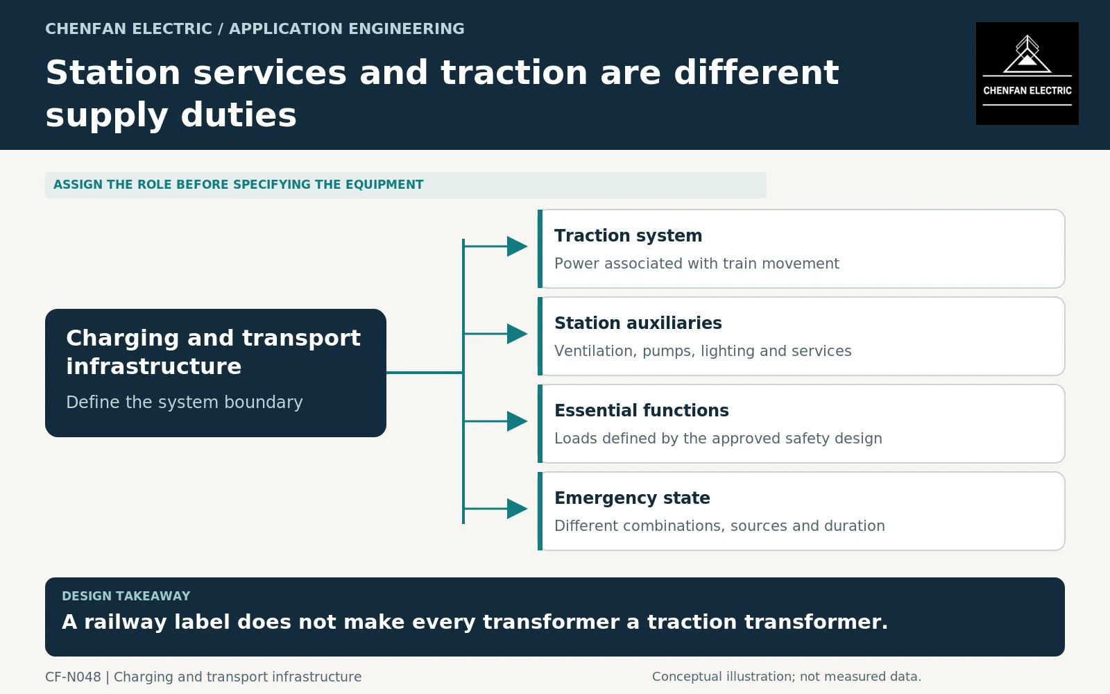
Locate the auxiliary boundary in the railway system
The single-line diagram should distinguish traction conversion, station distribution and any shared upstream supply. Identify whether auxiliary loads remain supplied when the traction section is unavailable and which alternate sources exist.
IEC 62695 addresses transformers for fixed railway installations, including traction and auxiliary functions within its scope. It does not mean that every station auxiliary transformer has the same duty as a traction transformer. [1]
Avoid using a traction rating or connection arrangement simply because it appears in another railway project. The required winding arrangement follows the actual source, load and grounding design.
Build a function-based load schedule
Separate continuous loads, intermittent services, motor loads and functions required during abnormal operation. Record electrical input, starting method, duration and permitted concurrency. A ventilation motor’s mechanical output rating alone is not a complete transformer input.
The essential-load classification must come from the responsible railway and safety design. This article does not determine which emergency systems are legally required or how long they must remain supplied.
| Load group | Duty information to obtain |
|---|---|
| Normal ventilation and pumps | Running current and start sequence |
| Lighting and small power | Coincident demand and phase distribution |
| Controls and communications | Continuity and backup-supply boundary |
| Emergency functions | Approved simultaneous loads and duration |
| Restoration | Restart order after a supply interruption |
Review emergency and restart states separately
Emergency operation can change both electrical demand and the local environment. Some loads stop while others start or run continuously. Do not assume that the normal diversity factor applies unchanged.
Motor-starting and sequence-of-events tools demonstrate the need to model motors with their source and starting arrangement. They are references for the analysis scope, not evidence that the station has already passed a study. [2] [3]
The transformer thermal assessment should also distinguish a short start from sustained emergency duty. Use the appropriate loading framework and the actual cooling conditions. For dry-type equipment, IEC 60076-12 provides a separate loading guide. [4]
Keep equipment and installation claims separate
Where dry-type transformers are selected, relevant equipment classifications do not replace the station’s fire, ventilation or emergency-power design. IEC 60076-11 addresses the transformer within its scope, not the complete metro station. [5]
The enquiry should include the auxiliary single-line diagram, normal and emergency load schedules, source-transfer cases and environmental conditions. Require the supplier to identify any duty restriction and the evidence supporting the proposed equipment.
Acceptance should reconcile the transformer schedule with the implemented station controls and backup supplies. A late change to ventilation staging or emergency operation can alter transformer duty without changing the normal connected-load total.
The final specification should make the distinction unmistakable: the transformer supports defined station services under defined operating states. Its railway location provides context, but the auxiliary function—not the presence of trains—determines the electrical duty.
Core procurement checkpoint: Keep station-service and traction core orders distinct
Metro auxiliary transformers should have their own approved design and procurement schedule. A project title containing ‘railway’ does not make an auxiliary core interchangeable with a traction design, nor does it establish onboard qualification. Identify the installation boundary and the actual manufacturing drawing, with separate packet labels and acceptance documents for each transformer type in the station package.
For the core enquiry: Auxiliary transformer design ID; core drawing; installation boundary; material specification; quantities and set identification.