

Short answer
A distribution transformer load centroid is the demand-weighted average position of the loads it will serve. Each load’s coordinates are multiplied by its demand, summed, and divided by total demand. In an illustrative service area with loads of 50, 30, 20 and 100 kW at four points, the centroid falls at about 115 m east and 58 m north of the origin, pulled toward the largest load. The centroid minimises the sum of load-weighted squared Euclidean distances, not the sum of ordinary weighted straight-line distances, which is only loosely related to what matters: cable route length along streets, voltage drop to the farthest customers, losses and cost. It may also fall in a road, a building or a site that cannot be used. Candidate sites near the centroid must be checked against route distance, voltage drop and land availability. The method is useful for early screening, not as a final siting answer.
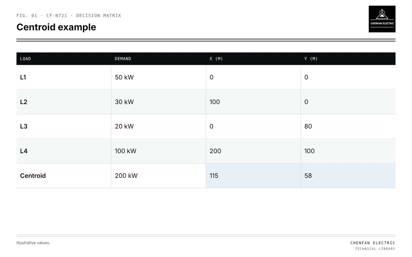
The centroid
| Load | Demand | x (m) | y (m) |
|---|---|---|---|
| L1 | 50 kW | 0 | 0 |
| L2 | 30 kW | 100 | 0 |
| L3 | 20 kW | 0 | 80 |
| L4 | 100 kW | 200 | 100 |
| Centroid | 200 kW | 115 | 58 |
x_c = Σ P_i x_i / Σ P_i, y_c = Σ P_i y_i / Σ P_i
Illustrative example. Four loads: 50 kW at (0, 0), 30 kW at (100, 0), 20 kW at (0, 80) and 100 kW at (200, 100), coordinates in metres. Values chosen for demonstration.
x_c = (0 + 3,000 + 0 + 20,000) / 200 = 115 m
y_c = (0 + 0 + 1,600 + 10,000) / 200 = 58 m
The 100 kW load dominates. Weighting by energy instead of peak demand gives a different point; the choice should match the planning objective.
What it minimises and what it ignores
| Considered | Ignored |
|---|---|
| Squared Euclidean distance weighted by load | Street routes and obstacles |
| Voltage drop, which depends on current and route | |
| Losses, which scale with current squared | |
| Land, access and permits | |
| Future load growth location |
A real loss objective must use current-squared resistance terms along the actual routes, including shared-section currents. Changing centroid weights alone does not minimise those network losses; minimising ordinary weighted distances instead gives a weighted geometric median, which need not equal the centroid.
Turning the centroid into candidate sites
- Map feasible sites near the centroid: verges, plots, existing poles.
- Measure route distance along streets to each load.
- Check voltage drop to the farthest and largest loads; see transformer siting under voltage-drop and service-reach constraints.
- Compare losses and cable cost for each candidate.
- Check transformer loading with realistic diversity; see correlated EV charging loads for new load types.
Where the method stops
- Large or irregular areas may need more than one transformer.
- Linear developments along a road put the centroid in the middle, but route-based optimisation may favour a different point.
- Uncertain future loads move the centroid; scenario planning helps; see planning transformer capacity with electrification scenarios.
- Sensitivity of the result to load estimates should be checked; see sensitivity ranking for planning inputs.
What this article does not cover
Whether one large transformer or two smaller ones should serve the area is a separate question and not covered here.
Where this reasoning stops. The centroid is a geometric aid; electrical and site checks decide.
Practical takeaway
Use the load centroid to find a starting area, then evaluate real candidate sites by route distance, voltage drop, losses and land, and revisit when load forecasts change.