

A GOES residual-stress depth profile needs a defined sampling volume at every depth. Pair spatial resolution with the stress result to distinguish a shallow surface effect from stress extending through a larger sheet volume.
Define the sampling volume at each depth
Define x across the track, y along it and z into the sheet from the treated face. Retain rolling direction on the same drawing. At every reported coordinate, mark the lateral footprint and depth sensitivity of the measurement. A probe centred on the line can include untreated material on both sides if its footprint is wider than the affected region.
Request stress components and signs with crystal orientation and diffraction elastic constants. A strongly textured measurement needs a suitable reflection and conversion; NPL discusses highly textured specimens [1]. Do not substitute an isotropic bulk constant without justification.
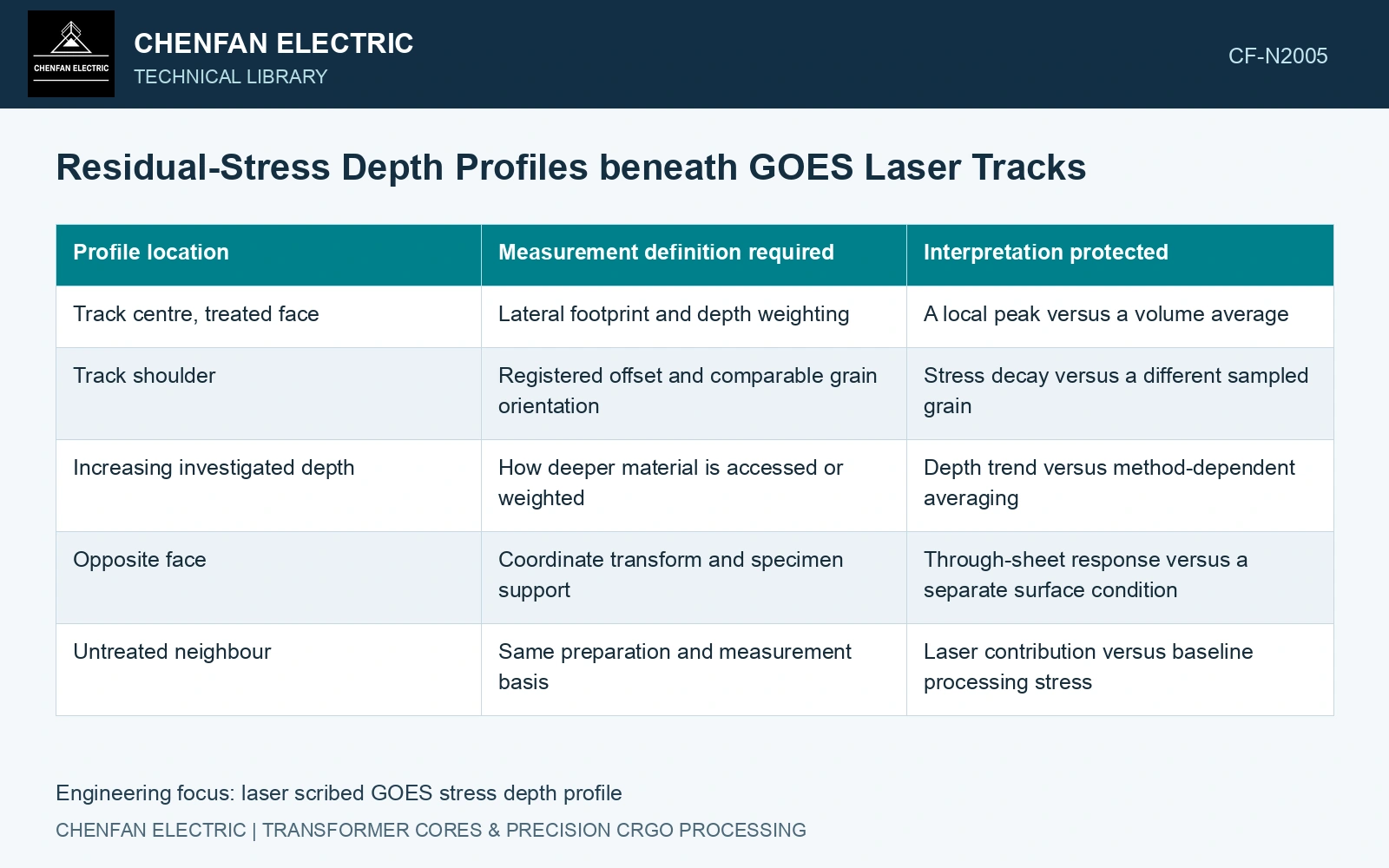
| Profile location | Measurement definition required | Interpretation protected |
|---|---|---|
| Track centre, treated face | Lateral footprint and depth weighting | A local peak versus a volume average |
| Track shoulder | Registered offset and comparable grain orientation | Stress decay versus a different sampled grain |
| Increasing investigated depth | How deeper material is accessed or weighted | Depth trend versus method-dependent averaging |
| Opposite face | Coordinate transform and specimen support | Through-sheet response versus a separate surface condition |
| Untreated neighbour | Same preparation and measurement basis | Laser contribution versus baseline processing stress |
Choose the depth route with the laboratory
X-ray intensity is depth-weighted and the weighting changes with geometry; NPL discusses penetration depth and steep gradients [1]. Establish the resolved sampling volume rather than assigning each result to an unsupported sharp depth.
For successive removal, account for redistribution/relaxation of the original stress, especially in thin sections [1]. Record thickness, preparation and correction basis. The measured newly exposed surface is not automatically the original stress at that depth.
Register stress and magnetic observations
Compare the investigated regions with domain observations made in a defined magnetic state. Preserve the different spatial and depth sensitivities of the two techniques. Similar-looking maps can have different averaging volumes, so point-by-point correlation may be unjustified.
Keep stress measurement and magnetic response tied to the same treatment coordinates. Laser-domain research demonstrates that treatment changes domain formation and magnetic behaviour, but it does not supply a universal stress-depth profile for another grade or beam condition. [2]
Catalogue gauge 0.23 mm corresponds to 230 μm thickness. [3] Assume sequential stress profiling removes 10 μm per step. After five removals, the remaining thickness is 180 μm: 21.74% of the original section has been removed. That section change can relax the stress field and alter the diffraction sampling geometry. Record each measured removal and apply a justified relaxation/measurement treatment before calling the sequence the original depth profile. Use an independent untreated witness to separate preparation-induced response from the laser-affected state.
Laser registration, initial residual stress, sectioning method and removal history define the inspected state. Keep destructive preparation outside the production acceptance comparison unless its influence is separately demonstrated.
Report stress, investigated depth, uncertainty and sampling volume together. Mark layers below the method’s resolution explicitly so a buyer can judge the proposed mechanism against physically located evidence.
References
- M. E. Fitzpatrick, A. T. Fry, P. Holdway, F. A. Kandil, J. Shackleton and L. Suominen, NPL Measurement Good Practice Guide No. 52: Determination of Residual Stresses by X-ray Diffraction, Issue 2, 2005, sections 5.4, 9.2 and 10.4.2.
- P. Rauscher et al., The influence of laser scribing on magnetic domain formation in grain oriented electrical steel visualized by directional neutron dark-field imaging, Scientific Reports 6, 38307, 2016, Table 1. DOI: 10.1038/srep38307.
- Nippon Steel Corporation, Grain-Oriented Electrical Steel Sheets, catalogue D004je, April 2020, specification and typical-property tables.