

Register the laser scan angle, rolling direction and magnetic test direction in one coordinate system. That shared reference turns a claim of transverse treatment into a reproducible geometry and performance comparison. [1]
Use a strip-fixed drawing
Mark rolling direction as x and transverse direction as y. Define scan angle θ from x, and mark which face is treated. Draw the actual line pattern, including its pitch definition. Keep this drawing with the cutting plan so that a coupon’s orientation remains traceable after it leaves the strip.
For an illustrative array of straight parallel tracks, let pn be their spacing measured normal to the tracks. Their intersection spacing along a rolling-direction path is pRD = pn/|sin θ|, when the path crosses the array. At θ = 90°, the two spacings are equal. At θ = 60°, the rolling-direction crossing distance is approximately 1.155 pn. As θ approaches zero, that path becomes parallel to the tracks and the crossing interpretation ceases to be useful.
This relation exposes a geometrical confounder. Holding a machine’s line-spacing field constant does not necessarily hold the spacing encountered along the magnetic direction constant. Establish which distance that field controls before calling an angle comparison matched.
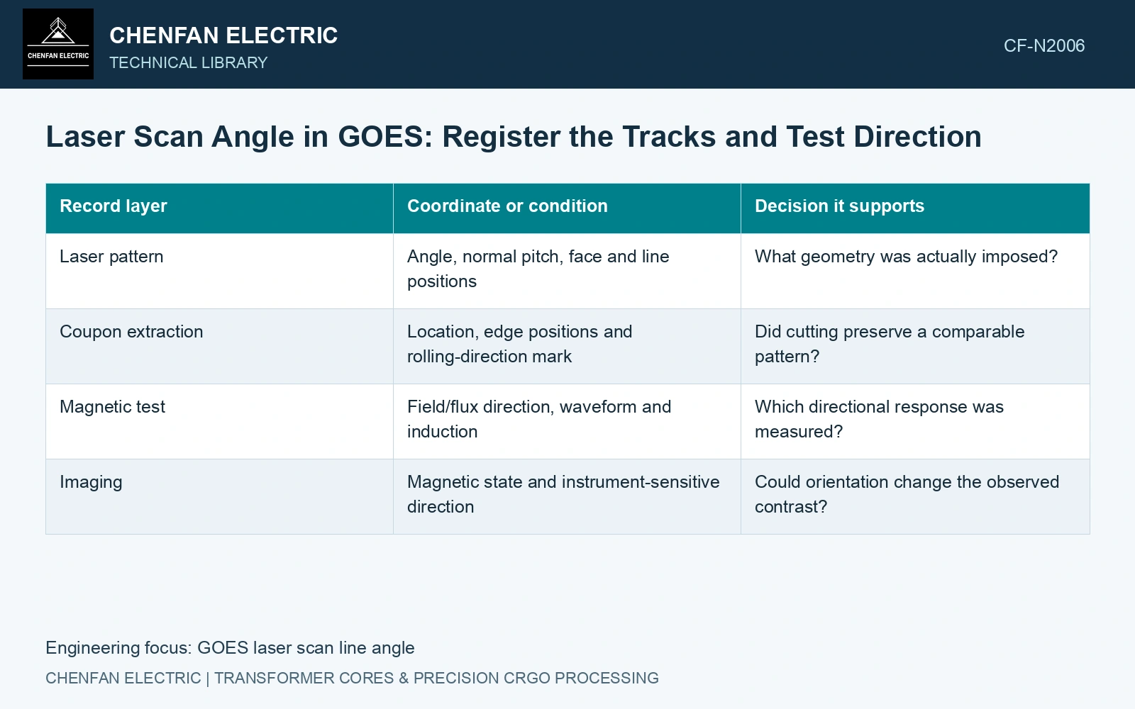
| Record layer | Coordinate or condition | Decision it supports |
|---|---|---|
| Laser pattern | Angle, normal pitch, face and line positions | What geometry was actually imposed? |
| Coupon extraction | Location, edge positions and rolling-direction mark | Did cutting preserve a comparable pattern? |
| Magnetic test | Field/flux direction, waveform and induction | Which directional response was measured? |
| Imaging | Magnetic state and instrument-sensitive direction | Could orientation change the observed contrast? |
Compare magnetic directions deliberately
First compare the rolling-direction duty at common induction, frequency and waveform. An additional off-axis or transverse comparison can investigate directional consequences, but it requires a fixture and interpretation suitable for that measurement. A test made by rotating the coupon without documenting changed edge, yoke or field conditions may add a measurement difference to the process difference.
Control incident energy, coating state and material position. If an angle change lengthens the scan path or changes the number of tracks within the tested area, retain those differences. Treat them as variables rather than attributing the entire response to θ.
Link scan geometry to the tested magnetic direction
The neutron study demonstrates that instrument orientation can reveal different domain structures. Changing contrast after rotation is therefore not direct evidence of improved magnetic performance. Couple the registered image with the corresponding global magnetic measurements. [1]
Assume line-normal pitch pₙ = 4 mm on catalogue 0.23 mm GOES [2]. RD crossing pitch is 4 mm at 90° and 4.619 mm at 60°. With assumed line energy q = 5 J/m, ideal energy per treated area q/pₙ stays 1,250 J/m²: angle alone has not changed line length per area. If instead RD crossing pitch is held at 4 mm, the 60° pattern requires pₙ = 4 sin60° = 3.464 mm; area energy becomes 1,443.4 J/m², 15.47% higher unless q is reduced. State which pitch and energy basis are controlled before attributing a magnetic difference to angle.
Scan angle, rolling-direction marking, pitch reference and cut datum determine the actual track layout. Avoid using a projected pitch from one axis as the physical line-normal spacing.
Specify the tested magnetic direction and line geometry on the supplied pieces. Select the pattern for the intended flux paths, with separate evidence for joint regions beyond the coupon test.
References
- P. Rauscher et al., The influence of laser scribing on magnetic domain formation in grain oriented electrical steel visualized by directional neutron dark-field imaging, Scientific Reports 6, 38307, 2016, Table 1. DOI: 10.1038/srep38307.
- Nippon Steel Corporation, Grain-Oriented Electrical Steel Sheets, catalogue D004je, April 2020, specification and typical-property tables.