

Harmonic phase angles can change the peak and shape of core flux even when harmonic voltage magnitudes are unchanged. A magnitude-only spectrum is therefore incomplete for reconstructing a time-domain flux trajectory. Preserve phase information when the design decision depends on waveform extrema, reversals or minor loops.
Integrating a harmonic changes its weighting
For an induced voltage component E_h sin(h omega t + theta_h), where E_h is peak amplitude, the centered flux contribution is -E_h cos(h omega t + theta_h)/(h omega N). [1] The factor 1/h reduces its flux amplitude relative to an equal-voltage fundamental component, but does not remove its phase dependence.
The total waveform is the sum of these time-aligned contributions. Its maximum does not generally occur at the maximum of every component. A table of voltage amplitudes alone cannot determine that instant.
Use a common phase reference, usually tied to a specified fundamental component. A phase angle without its reference or polarity convention cannot be combined reliably with another dataset.
Convert every phase to the same fundamental reference
For phase comparison, write the fundamental as E_1 sin(omega t + theta_1) and set x = omega t + theta_1. The h-th harmonic is then E_h sin(hx + alpha_h), where alpha_h = theta_h – h theta_1, modulo 2pi. This relative phase is unchanged by a common shift of the time origin. Subtracting theta_1 only once from every harmonic would be incorrect.
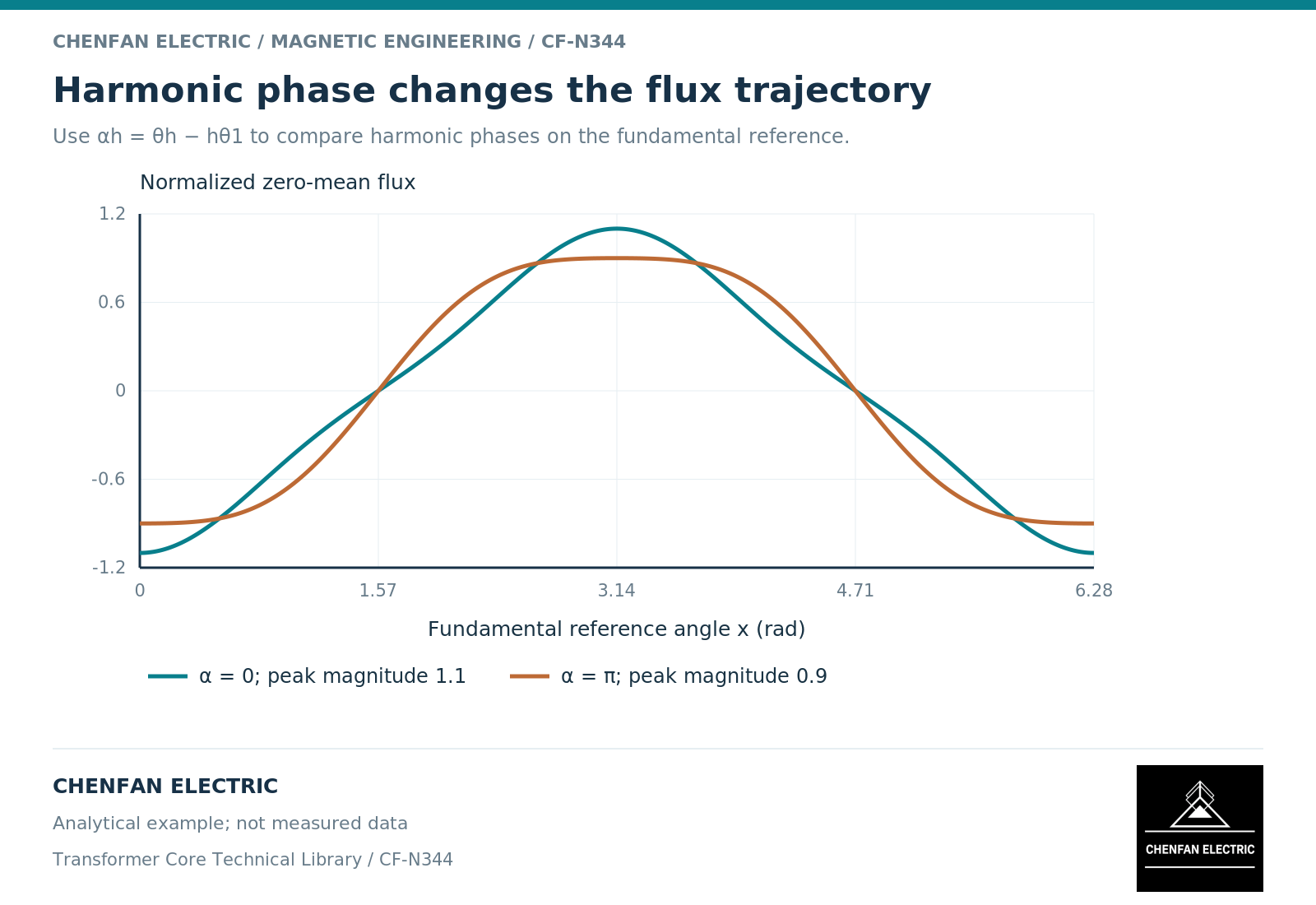
For an illustrative third harmonic, theta_1 = 30 degrees and theta_3 = 90 degrees give alpha_3 = 0 degrees. Keeping theta_1 at 30 degrees but setting theta_3 = 270 degrees gives alpha_3 = 180 degrees. At a third-harmonic voltage amplitude of 0.3 times the fundamental, the figure shows the resulting normalized centered fluxes, -cos(x) – 0.1 cos(3x) and -cos(x) + 0.1 cos(3x).
Their peak magnitudes are 1.1 and 0.9 respectively, with no residual offset assumed. The distinctive handover issue is not just retaining an angle: it is retaining the fundamental reference, harmonic order and sign convention that make that angle usable. The numerical waveforms remain analytical examples, not measured records.
Phase information matters beyond the largest peak
A harmonic can alter local slopes or introduce additional reversals in the flux trajectory. Those reversals can affect the magnetic-history path even when the overall peak-to-peak excursion changes little.
A frequency-domain effective material model is not necessarily designed to reproduce every time-domain reversal or harmonic interaction. Model guidance distinguishes effective frequency-domain behavior from a full transient constitutive description. [2]
The required detail depends on the objective. A screening estimate of fundamental flux may tolerate a simplified spectrum. A minor-loop loss prediction or transient current calculation needs a waveform representation compatible with that objective.
Preserve the complex spectrum in the handover
The data package should retain harmonic order, absolute frequency, amplitude definition and phase angle for each relevant component. Also provide the time record where available, especially when the waveform is not stationary over the analyzed interval.
| Data issue | Consequence |
|---|---|
| Missing phase angles | Peak reconstruction becomes non-unique |
| Different phase references | Components cannot be combined directly |
| Peak versus root-mean-square mismatch | Incorrect amplitude scaling |
| Unsynchronized channels | Incorrect interphase flux relationship |
| Changing waveform during analysis | A single spectrum may not represent the event |
When phase information is unavailable, state that limitation and use justified bounding cases rather than presenting one reconstructed waveform as unique. The bound should be labeled as a study assumption, not a measured operating condition.
The practical lesson is to retain the information that determines the decision. Harmonic magnitudes are valuable, but they are only part of the excitation definition when peak flux, waveform asymmetry or magnetic-history effects matter.
References
[1] Lloyd Dixon / Texas Instruments. Magnetics Design 1 – Introduction and Basic Magnetics.
[2] Nirmal Paudel / COMSOL. Model Magnetic Materials in the Frequency Domain with an App (2016).