

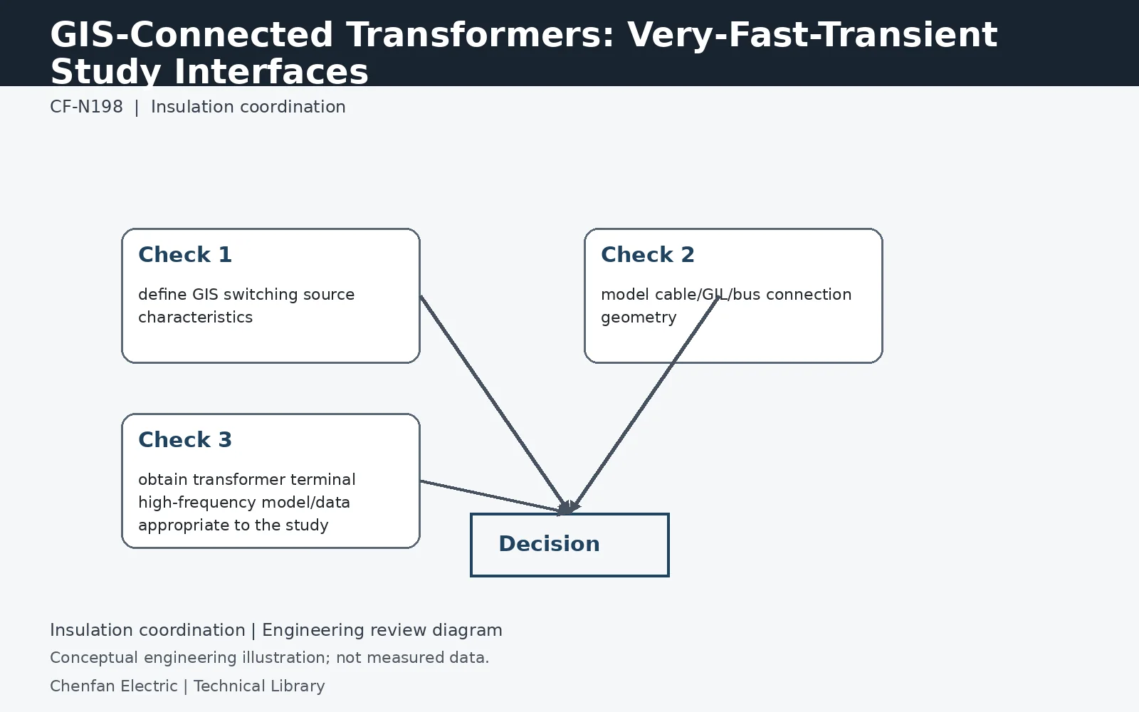
GIS-connected transformers may require a very-fast-transient assessment when the switching and connection arrangement produces relevant fast-front stresses. The interface depends on GIS behavior, propagation paths and the transformer’s frequency-dependent response. Data exchange among the GIS, connection and transformer suppliers is therefore part of the insulation-coordination scope.
Fast-front behavior requires a suitable bandwidth
Some GIS switching events involve repeated breakdowns and fast travelling waves whose important frequency content extends beyond a conventional power-frequency transformer equivalent. The GIS compartments, connections and transformer terminal response must be represented over the band needed to resolve the decision. A leakage impedance measured at 50 or 60 Hz cannot by itself describe that interface. The study should state its frequency and time-resolution limits rather than labeling a model “high frequency” without qualification.
Connection type changes what reaches the winding
A direct GIS connection, an intervening cable and an overhead transition present different propagation and reflection paths. Length, impedance discontinuities, grounding geometry and protective-device placement influence the terminal waveform. The transformer manufacturer may need a terminal voltage envelope or a suitable time-domain waveform to assess internal stress. A low terminal peak alone does not necessarily settle a steep-front winding-distribution question, so agree the required output with the manufacturer before running the study.
Assign the data exchange across all suppliers
The GIS supplier provides applicable switching and layout data; the connection supplier provides cable or bus parameters; the transformer supplier provides an appropriate terminal model or agreed assessment boundary. The system engineer integrates them and documents uncertainty, including initial charge and switching variations where relevant. The final report should distinguish standard dielectric test evidence from the installation-specific transient assessment. Neither party should assume that another supplier's catalogue rating alone closes the interface.
Technical reference framework
[1] IEC 60071-1:2019 — Insulation co-ordination, Definitions, principles and rules.
[2] IEC 60071-2:2023 — Insulation co-ordination, Application guidelines.
[3] IEC 60076-3:2013 + AMD1:2018 — Insulation levels, dielectric tests and external clearances.
[4] IEEE C57.98-2026 — Transformer impulse tests.