

A hybrid interface can place gas on one side of a bushing and oil on the other. Define both pressure states at the seal elevation using the same reference; fluid pressure and hydrostatic head enter the interface load [1]. Retain the actual barrier and every possible migration path.
The first drawing should show where each fluid stops. Identify the central barrier and every seal, test connection or internal passage that could connect the two sides. Do not infer these paths from an external outline or a catalogue voltage rating.
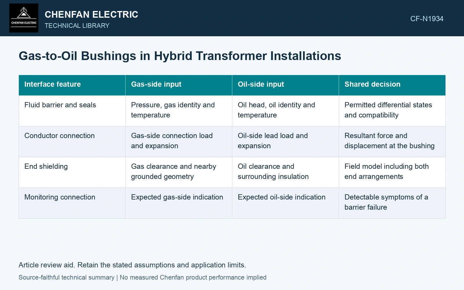
Compare simultaneous states
Define ΔP = Pgas − Poil at the relevant sealing interface, with pressures in pascals on the same absolute reference. Oil pressure depends on the actual oil head and operating arrangement. A tank-top pressure reading may need an elevation correction before comparison with pressure at the bushing seal.
Consider normal operation, cold standby and the manufacturer’s permitted maintenance states. Either sign of ΔP may occur if one side is emptied, cooled or depressurized. A seal qualified only for one direction requires particular attention when the opposite state is proposed.
| Interface feature | Gas-side input | Oil-side input | Shared decision |
|---|---|---|---|
| Fluid barrier and seals | Pressure, gas identity and temperature | Oil head, oil identity and temperature | Permitted differential states and compatibility |
| Conductor connection | Gas-side connection load and expansion | Oil-side lead load and expansion | Resultant force and displacement at the bushing |
| End shielding | Gas clearance and nearby grounded geometry | Oil clearance and surrounding insulation | Field model including both end arrangements |
| Monitoring connection | Expected gas-side indication | Expected oil-side indication | Detectable symptoms of a barrier failure |
Trace migration before choosing an alarm
A pressure difference can drive fluid through an unintended path. Which fluid moves first depends on the path and current differential. The review should ask where migrated gas or oil would collect and which installed measurement could see it. A sensor on one tank does not necessarily detect a small migration confined inside the bushing assembly.
Record the difference between an external leak and cross-media leakage. The latter can change insulation conditions without creating an obvious wet surface outside the equipment. A joint-tightness result needs to state which leakage path it actually assessed.
Put loads through the common support
Gas duct movement and oil-side lead movement can act on the same conductor or flange. Combining each supplier’s maximum load independently may be either overly conservative or incomplete; first identify which load cases can occur together. Retain their directions and support stiffnesses.
Assume seal-level gas/oil pressures 300/150 kPa absolute and effective area 0.010 m²: ΔP = 150 kPa and axial force 1,500 N [1]. Against an assumed 1,600 N forward-load screen it passes. A second assumed state of 100/200 kPa gives −1,000 N; the first result cannot qualify that reversed direction. Hold any unqualified state and obtain the shared differential-pressure/temperature envelope. Plan verification within an approved pressure-test boundary, including stored-energy controls [2]; these values are fictional, not test instructions.
End shields also depend on the installed surroundings. A shield drawing accepted with one gas enclosure diameter or oil-side lead route cannot be transferred silently to another. The final interface review should contain the shared assembly geometry and simultaneous state combinations, so neither side’s acceptance leaves an unexamined condition inside the bushing.
References
- U.S. Department of Energy, DOE-HDBK-1012/3-92, Thermodynamics, Heat Transfer, and Fluid Flow, Volume 3, 1992.
- UK Health and Safety Executive, Safety requirements for pressure testing, Guidance Note GS4, fourth edition, 2012.