

A floating conductive part near a core can acquire an electrical potential through coupling to surrounding energized and grounded structures. Its potential is not necessarily zero simply because it has no intentional power connection. The design question is how that part’s potential and insulation stresses are controlled in the complete assembly.
Think in capacitances as well as physical distances
In a simple electrostatic illustration, an isolated conductive part is capacitively coupled to surrounding nodes. Its potential depends on those capacitances, the node voltages and any initial charge. For an initially neutral node coupled only through ideal capacitors, charge balance gives a capacitance-weighted potential.
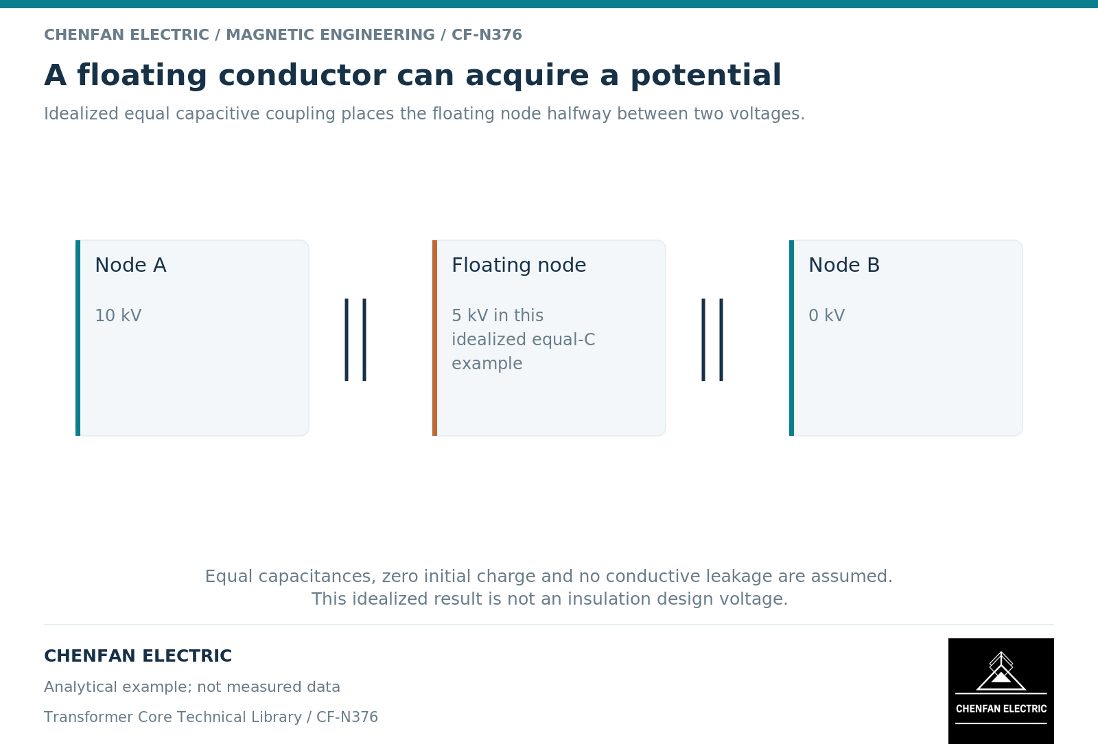
As an illustrative two-capacitor example, equal capacitances to a node at 10 kV and to a reference at zero potential place the floating node at 5 kV. This is an idealized calculation, not a transformer insulation rating or a prediction for a real component.
Core-grounding research uses distributed capacitive relationships to explain potential-control and ground-current behavior. [1] Real assemblies require more nodes and dielectric geometry than the two-capacitor sketch.
Separate electrostatic isolation from magnetic exposure
A part can be electrically isolated from surrounding metal and still experience an alternating magnetic field. If it is conductive, local eddy-current circulation may occur within it even without an external electrical connection. Electromagnetic field formulations distinguish conductivity from the specification of a component’s electrical potential. [2]
Therefore, “floating” does not mean “no induced current,” and “grounded” does not mean “no heating.” The electrostatic and magnetic reviews answer different questions.
The geometry of edges, gaps and nearby insulation also matters. A simple average potential does not describe every local electric-field concentration. Local dielectric evaluation requires the actual shape and surrounding materials.
Identify parts by function and intended state
| Part or interface | Question for the design record |
|---|---|
| Separate shield or screen | What potential is intended and how is it established? |
| Insulated clamp component | Which electrical boundary must remain intact? |
| Lead support with metal inserts | Are all conductive inserts included in the node map? |
| Removable assembly section | Does its electrical state change after integration? |
| Temporary hardware | Is it present in the evaluated service configuration? |
The appropriate treatment is not automatically to connect every metallic item to the same point. That could conflict with intentional insulation or create an unwanted conducting loop. Conversely, leaving a part isolated without a defined dielectric design is not a complete solution.
Review the final assembly rather than isolated components
The original equipment manufacturer should define the electrical role of each relevant conductive part, its intended connections or isolation, and the evidence required after assembly. The core supplier needs the corresponding interface requirements for its delivered scope.
A useful review package combines an electrical node map, the mechanical locations and the associated insulation boundaries. It should identify uncertain contacts and temporary states explicitly. A drawing symbol that is not traceable to the physical part is insufficient.
This is an electrostatic design review, not a field instruction to add or remove grounds. The actionable result is a controlled decision about each part’s electrical state and dielectric environment. It prevents unconnected metal from being overlooked while avoiding the equally unsafe assumption that one grounding treatment is suitable for every component.
References
[1] Xiu Zhou and coauthors / Frontiers in Energy Research. Analytical modeling and calculation of core grounding current in converter transformer (2023).
[2] David Meeker. Finite Element Method Magnetics User Manual.