

Thin core laminations sag and twist beyond their rigid CAD outline. Build collision checks around the validated deflection envelope for the actual grip, unsupported spans and support transitions.
Separate pose from shape
Describe a point on the part as its rigidly transformed location plus a deformation relative to that rigid shape. The deformation can depend on gravity orientation, support spacing, grip condition and the motion history. It should not be folded into a single tool-centre offset.
Map the supported and unsupported regions at picking, transfer, turning, approach and release. Add the transitions where one support engages or disengages. The greatest deflection may occur between the named waypoints, so endpoint checks alone are insufficient.
Build a swept envelope
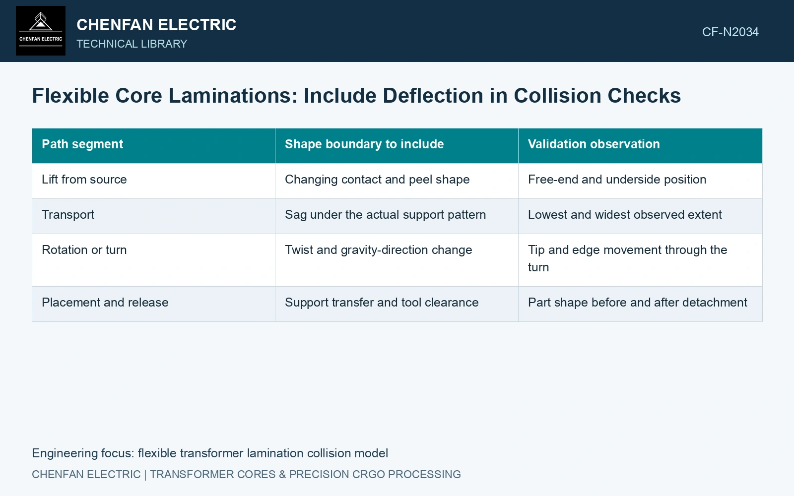
| Path segment | Shape boundary to include | Validation observation |
|---|---|---|
| Lift from source | Changing contact and peel shape | Free-end and underside position |
| Transport | Sag under the actual support pattern | Lowest and widest observed extent |
| Rotation or turn | Twist and gravity-direction change | Tip and edge movement through the turn |
| Placement and release | Support transfer and tool clearance | Part shape before and after detachment |
The envelope should contain the predicted deformation and a justified allowance for model error, part variation and pose uncertainty. Combining unrelated worst-case scalar allowances can be excessively conservative or miss a directional effect. Retain the directions and conditions responsible for each boundary.
Validate where the model is weakest
Use representative long spans, wide overhangs and contact configurations in a controlled commissioning arrangement. Observe the shape with adequate views; an occluded tip cannot validate its predicted clearance. Compare measured envelopes with the model along the path, including acceleration and settling where relevant.
NIST robot assessment research separates geometric and non-geometric tool-position/orientation errors from measurement uncertainty. Use that distinction to qualify the actual measurement chain; flexible-sheet shape and camera visibility still require their own application-specific evidence. [1]
Keep qualification tied to the part family
A shorter but thinner part may deform differently from the longest part. A new contact pattern can also change the governing span. Qualify the relevant geometry and support boundaries rather than assuming that one largest outline covers every flexible condition.
Use catalogue gauge t = 0.23 mm and density 7,650 kg/m³ [2]. Assume simply supported spans, width 0.20 m, E = 200 GPa and static self-weight. With I = bt³/12 and w = ρbtg, δ = 5wL⁴/(384EI) gives 69.3 mm at L = 0.50 m, outside a reliable small-deflection shape prediction. At L = 0.10 m it gives 0.111 mm and δ/L = 0.00111, suitable for a preliminary small-deflection screen. Assume 1.0 mm nominal obstacle clearance, a 0.40 mm combined directional pose/model allowance and a required 0.50 mm remaining clearance. The budget is 1.0 − 0.111 − 0.40 = 0.489 mm: reject that layout. Increasing nominal clearance to 1.1 mm gives 0.589 mm. Validate the actual tool-pose uncertainty [1], sheet shape, acceleration and support transitions before qualifying the changed path.
Support spacing, grip locations, sheet flatness and motion acceleration control the flexible envelope. Include released residual shape and tip motion rather than checking collision with the nominal CAD plane alone.
Use the validated envelope for the approved motion review. Reassess clearance when the production lamination, grip or support state falls outside the model’s verified range.
References
- G. Qiao and B. A. Weiss, Industrial Robot Accuracy Degradation Monitoring and Quick Health Assessment, Journal of Manufacturing Science and Engineering 141, 2019. DOI: 10.1115/1.4043649.
- Nippon Steel Corporation, Grain-Oriented Electrical Steel Sheets, catalogue D004je, April 2020, specification and typical-property tables.