

A core-gripper tool change resets the coupling, contact and loaded-placement conditions. Validate reseating together with the released lamination features that define acceptance for each part family.
Separate the error sources
Measure a stable reference on the reattached tool before loading a part. This identifies changes in tool position and orientation relative to the robot. Then measure a representative lamination held by the tool. Its change relative to the tool reveals seating and support effects that an unloaded reference cannot capture. [1]
Finally inspect the released part at the target. That includes placement and detachment behaviour. These observations answer different questions and should remain separately available when a discrepancy is investigated.
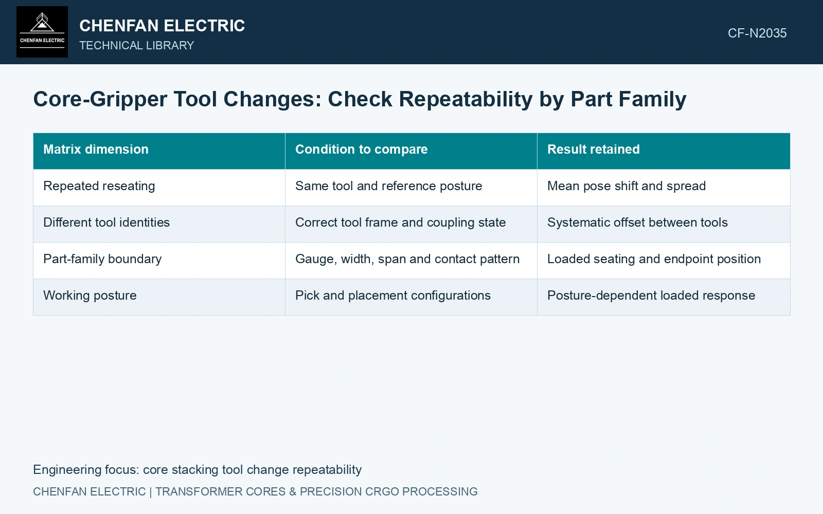
| Matrix dimension | Condition to compare | Result retained |
|---|---|---|
| Repeated reseating | Same tool and reference posture | Mean pose shift and spread |
| Different tool identities | Correct tool frame and coupling state | Systematic offset between tools |
| Part-family boundary | Gauge, width, span and contact pattern | Loaded seating and endpoint position |
| Working posture | Pick and placement configurations | Posture-dependent loaded response |
Use a reference that represents the working part
A short rigid reference piece may reveal coupling repeatability while missing a long sheet’s angular amplification and sag. Use it for its intended purpose, then add the representative loaded check. Cover part families that change contact coverage or overhang, not only those with the largest mass.
Repeat the detach-and-reattach cycle sufficiently to estimate spread under the defined conditions. Retain the first and later cycles rather than discarding early results without an established reason. Wear, debris or an incompletely seated coupling can create a progressive change.
Determine whether a correction is repeatable
A consistent mean offset may be addressed through an approved frame correction followed by verification. Variable reseating cannot be fixed by one offset. Check coupling condition, part seating and measurement uncertainty before adding calibration adjustments.
NIST robot accuracy research separates constant and position-dependent errors and emphasizes measurement uncertainty. Those principles apply to interpreting this matrix, but the paper does not establish a tool-changer’s performance on a core-stacking application. [1]
Use a 0.23 mm catalogue sheet as the reference part. [2] Assume a tool-change repeatability study finds normal offsets of −0.06, +0.02 and +0.08 mm for three independent installations. The observed range is 0.14 mm, or 61% of one nominal gauge. Under an assumed ±0.05 mm placement-error allocation, two installations fail the screen. Re-seat or recalibrate the tool and repeat the family-specific placement check. A small mean offset of 0.013 mm does not remove the extremes or demonstrate reliable step-lap placement. [1]
Tool seating, vacuum-pad height, sheet support and end-point registration belong to the released part-family setup. Check both position and orientation after a tool change, particularly on long laminations.
Approve the tool identity, frame revision and part-family range together using both coupling repeatability and loaded, released feature positions.
References
- G. Qiao and B. A. Weiss, Industrial Robot Accuracy Degradation Monitoring and Quick Health Assessment, Journal of Manufacturing Science and Engineering 141, 2019. DOI: 10.1115/1.4043649.
- Nippon Steel Corporation, Grain-Oriented Electrical Steel Sheets, catalogue D004je, April 2020, specification and typical-property tables.