

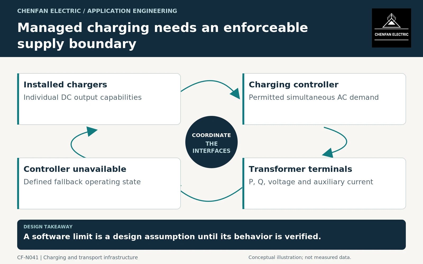
Managed charging can reduce the simultaneous demand of an electric-vehicle charging hub, but the transformer specification must use an enforceable alternating current (AC) operating envelope. Adding charger direct current (DC) output ratings can overstate normal demand, while assuming a diversity factor without control evidence can understate it. Define the aggregate input limit, its measurement boundary and the behavior when the controller or communications are unavailable.
Convert charger output into the actual supply duty
Charger output power is delivered on the vehicle side. The upstream AC demand also reflects conversion losses, auxiliaries and the charger’s input characteristics. Obtain the AC current or P-Q envelope for the proposed equipment and operating voltage.
IEC 61851-23 addresses DC electric-vehicle supply equipment within its scope. Its use does not determine the coincidence of a particular site’s chargers or the rating of the upstream transformer. [1]
For an illustrative site with ten 300 kW DC chargers, 3 MW is the installed sum of output capability. A controller may limit aggregate AC input to a different value, but that limit must be defined in AC terms and include whatever station loads share the transformer. Neither number alone establishes transformer MVA.
Specify the controller as part of the duty basis
Identify where current or power is measured, how the limit is allocated and how quickly the system responds to new sessions or other loads. State whether the limit applies to active power, apparent power or current. These are not equivalent controls when reactive power or voltage varies.
The fallback state is particularly important. Communication loss, meter failure, controller restart and an added charger should have defined behavior. A design depending on managed demand must not silently allow every charger to revert to unrestricted output when management is lost.
| Control input | Required evidence |
|---|---|
| Aggregate limit | Quantity, units and measurement boundary |
| Charger allocation | Supported equipment and permitted concurrency |
| Auxiliary inclusion | Which station loads count toward the limit? |
| Failure behavior | Documented fallback for lost control or measurement |
| Change management | Review when chargers or firmware are added |
Evaluate the charging schedule thermally
The controller cap defines a possible maximum, but the duration and repetition of high demand still matter. Queue behavior, customer dwell time and charging curves can create a different daily sequence from the sum of charger ratings.
Use an equipment-appropriate loading assessment with the actual ambient and cooling conditions. Mineral-oil and dry-type loading guides provide different frameworks and should be applied within their own scopes. [2] [3]
Do not treat a brief charging peak and a sustained plateau as interchangeable. Equally, do not assume that every vehicle draws its charger maximum for the entire session. The schedule should be based on stated fleet or site assumptions, with uncertainty made visible.
Compare transformer offers against the same managed envelope
Issue the charger AC data, controller limit, fallback matrix, station auxiliary list and representative operating schedule. Ask each supplier to state the duty used in its assessment and any dependency on an enforced restriction.
General transformer application guidance supports matching ratings and operating conditions, but it does not validate the charging controller. [4] Verification of the control boundary belongs to the site integration and acceptance plan.
The purchasing decision is defensible when the reduced demand is a documented system capability, not merely an optimistic utilization forecast. Managed charging can be part of transformer sizing; it cannot be treated as a free diversity allowance without specifying how that allowance remains true in operation.
Core procurement checkpoint: Use the approved charging strategy before freezing the core
Managed charging can change the operating cases used to select the transformer, but the software’s power limit is not a core drawing. Order the core against the design approved for the agreed voltage, frequency and loading envelope. Keep the controller revision or operating-limit reference in the equipment documentation so that a later charging-policy change prompts a design review rather than an assumed spare capacity.
For the core enquiry: Approved equipment design; core geometry; charging-limit revision reference; material specification; delivery and acceptance scope.