

An encapsulated air-core reactor needs a mapped surface-water route and separate evidence against ingress. Where an IP degree is specified, IEC 60529 concerns the defined enclosure boundary; resin coating alone does not assign that protection. [1] Trace retained water, cracks and interfaces as well as visible runoff.
Trace water from the top of the installed winding to the discharge point. Include coil ribs, layer grooves, support interfaces and terminal details. Use the actual installation angle and orientation; a horizontal workshop sample may drain differently from the assembled reactor.
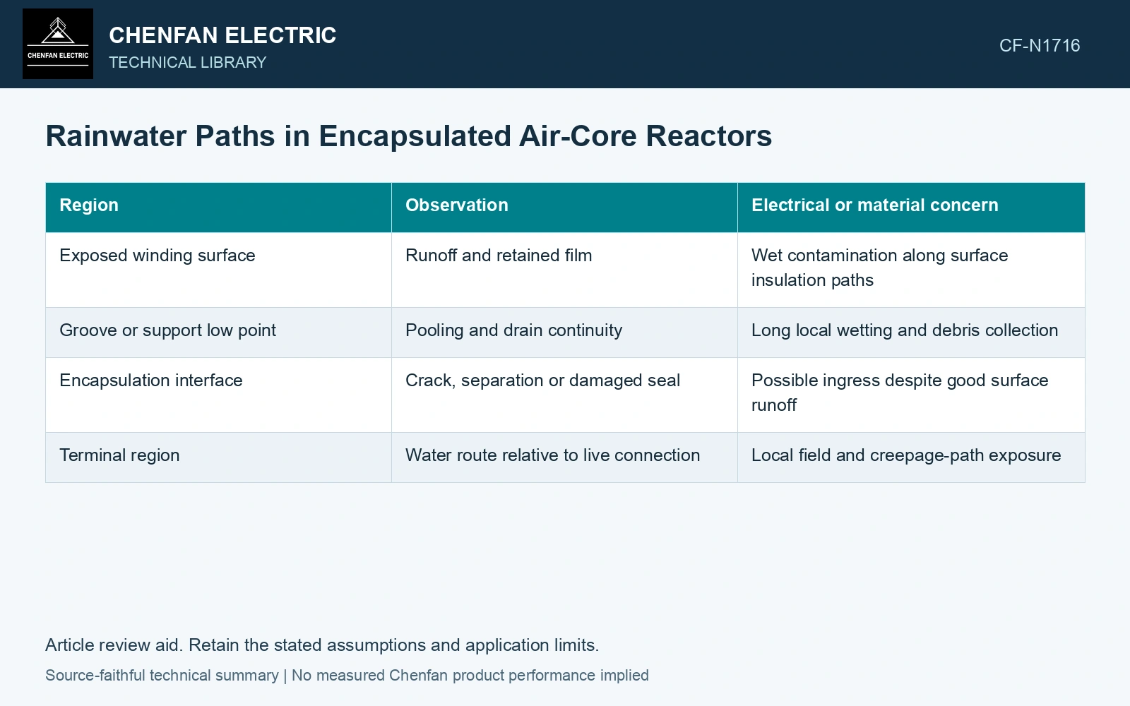
Inspect a complete water path
| Region | Observation | Electrical or material concern |
|---|---|---|
| Exposed winding surface | Runoff and retained film | Wet contamination along surface insulation paths |
| Groove or support low point | Pooling and drain continuity | Long local wetting and debris collection |
| Encapsulation interface | Crack, separation or damaged seal | Possible ingress despite good surface runoff |
| Terminal region | Water route relative to live connection | Local field and creepage-path exposure |
Compare dry and wet conditions deliberately
Photograph the same locations before wetting, during runoff and after the defined observation interval. Identify residual pools rather than reporting only that water leaves the coil somewhere. Retain temperature and contamination condition because they affect wetting and drying.
Keep visual drainage observations separate from the equipment’s qualified wet electrical and environmental evidence. A runoff map describes geometry and material condition; it does not establish withstand or sealed-ingress performance.
Relate retained volume to measured drainage flow over the relevant observation period. The volume-flow relation does not establish encapsulation permeability or electrical strength. [2]
Trace the retained-water drainage boundary
Assumptions: a 0.20 m² horizontal pocket holds 5 mm equivalent water depth, giving 0.20 × 0.005 = 0.001 m³ or 1 L. Rain has stopped; the verified drain passes a constant 0.25 L/min over this volume, while the project requires clearance within 2 min. Drain time is 4 min, exceeding the allocation by 2 min. Hold that drainage detail; at least 0.50 L/min would be needed under this ideal volume balance. Inspect the actual pocket and interfaces separately from dielectric and ingress qualification. [2]
References
- IEC, IEC 60529:1989+AMD1:1999+AMD2:2013 CSV, Degrees of protection provided by enclosures (IP Code).
- U.S. Department of Energy, DOE-HDBK-1012/3-92, Thermodynamics, Heat Transfer, and Fluid Flow, Volume 3, 1992.