

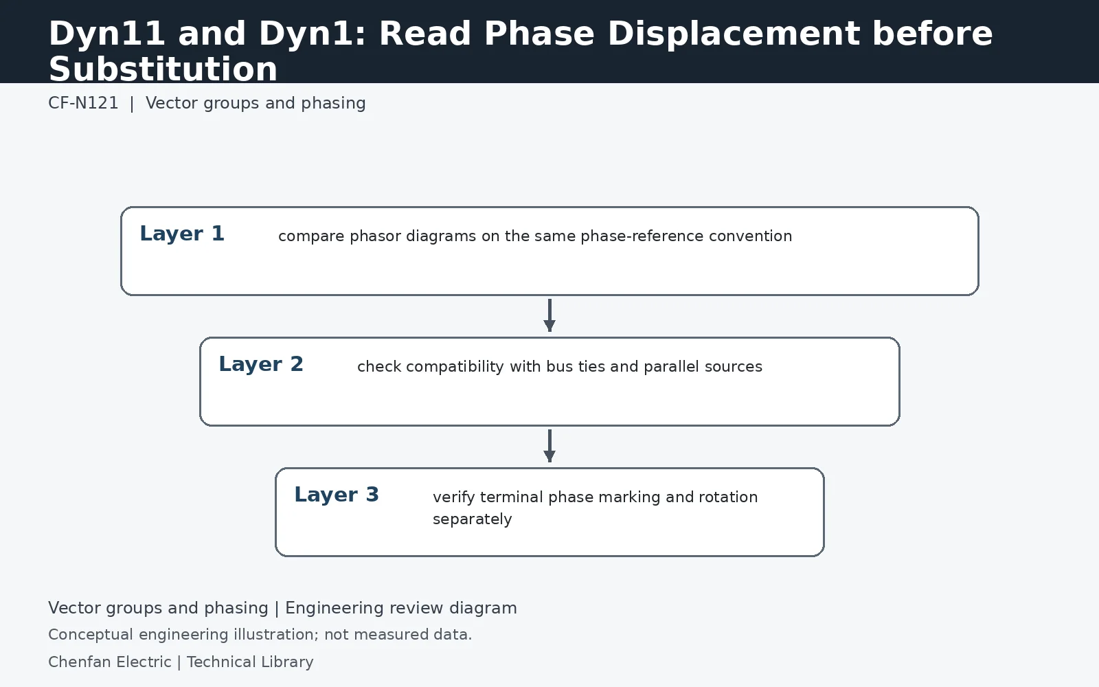
Dyn11 and Dyn1 are not interchangeable labels: the clock number represents a different phase displacement between high- and low-voltage systems. Substituting one for the other can create a phase-angle mismatch with existing transformers, generators, converter interfaces or bus ties. Check the project phasor convention and phase identification rather than relying only on the familiar connection letters.
What the clock number adds to the letters
D identifies a delta-connected higher-voltage winding; y identifies a star-connected lower-voltage winding; n indicates an accessible lower-voltage neutral. Those letters do not establish the angular relationship. Under the usual IEC clock convention, Dyn11 represents a 30° low-voltage lead and Dyn1 a 30° lag relative to the defined high-voltage reference. Their relative displacement differs by 60° under that convention. The complete phasor diagram and terminal designation must accompany the connection symbol whenever equipment from different drawings or manufacturers is compared.
Where a phase mismatch becomes a system problem
An isolated load supplied by only one transformer has a different interface from a bus that can be tied to an existing source. Parallel transformers, closed-transition transfer systems, converter bridges and differential protection all use phase references. A changed group can therefore invalidate otherwise correct voltage and ratio data. Check every permitted coupling path, including maintenance arrangements that are seldom used. A phase-sequence meter confirming the same rotation is not sufficient evidence that voltages across a prospective coupling point have the required displacement.
Approve the connection before releasing manufacture
The replacement data sheet should identify the required group, phase labels, grounding arrangement, CT compensation and any interface that forbids a change. Resolve discrepancies through an approved connection study and manufacturer drawings. Do not present a general terminal-swapping shortcut as a site solution: the consequences depend on both sides' phase references and connected protection. Keep commissioning verification of terminal correspondence, rotation and displacement as separate acceptance records. A correct nameplate symbol verifies the ordered design, not every field connection.
Technical reference framework
[1] IEC 60076-8:1997 — Application guide.
[2] IEEE C57.105-2019 / Cor 1-2023 — Three-phase transformer connections.