

Peel-off picking separates thin CRGO through controlled curvature. Screen the trajectory’s geometric exposure, then measure unloaded recovery, coating condition and single-sheet transfer.
Draw the supported shape throughout the motion
Mark the support point, gripping contacts, free span and opening edge. Record the sequence from first contact through gap formation, transfer and release. The location of maximum curvature may move as contact changes. A photograph of the final lifted position can miss a sharper bend earlier in the cycle.
For simple pure bending, outer-fibre geometric strain is approximately ε = t/(2R), with gauge t and neutral-surface radius R in the same units. This approximation describes exposure; it supplies no material yield or coating-damage threshold.
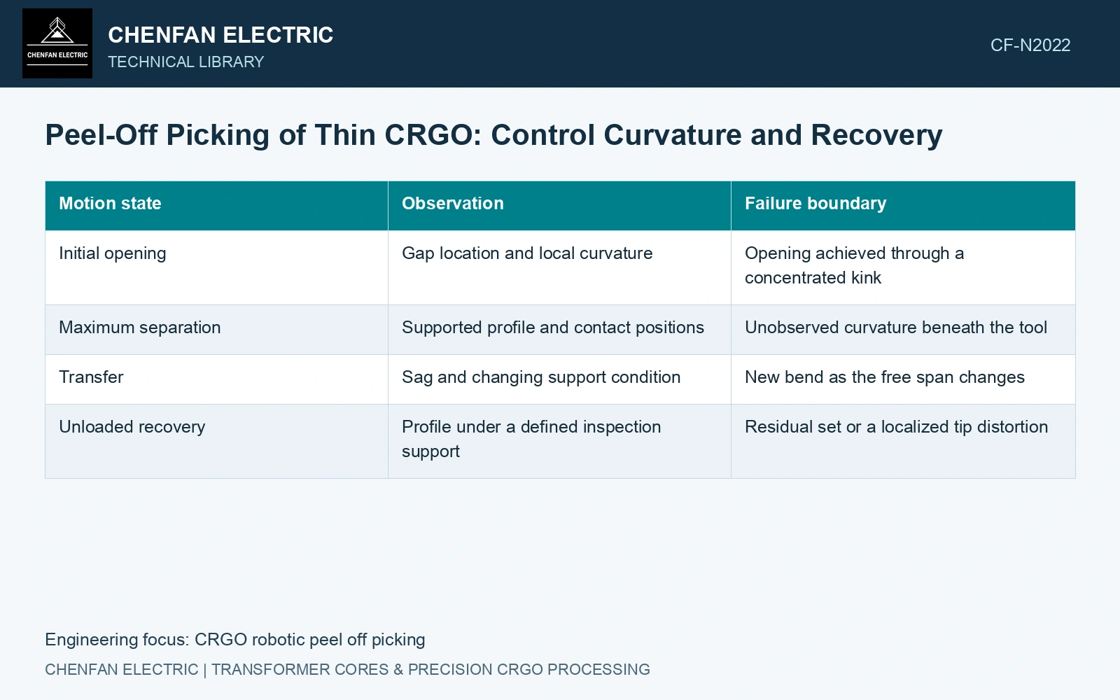
Observe the recovery path
| Motion state | Observation | Failure boundary |
|---|---|---|
| Initial opening | Gap location and local curvature | Opening achieved through a concentrated kink |
| Maximum separation | Supported profile and contact positions | Unobserved curvature beneath the tool |
| Transfer | Sag and changing support condition | New bend as the free span changes |
| Unloaded recovery | Profile under a defined inspection support | Residual set or a localized tip distortion |
Compare the unloaded shape with the pre-pick shape using the same supports and orientation. Gravity can change the measured profile, especially on a long sheet. Residual curvature cannot be identified by comparing a suspended after-image with a flat-table before-image.
Include coating and repeated handling
Inspect the regions of greatest bending and tool contact for a repeatable change in surface condition. The absence of permanent metal bending does not establish that the coating was unaffected. Conversely, a visible contact mark requires investigation rather than an automatic claim of insulation failure.
Test the lamination families that bound the intended application: free-span length, width, gauge, cut-end shape and surface condition. Include repeated picking if a part can be handled more than once. Vacuum holding capacity and a reliable seal are necessary, but they do not define the bending produced by the contact arrangement.
Use catalogue t = 0.23 mm [1]. Assume independent standard uncertainties uₜ = 0.005 mm and uᵣ = 5 mm. At assumed R = 100/200 mm, ε is 0.1150%/0.0575%; propagation gives uε = 0.00627%/0.00190% [2]. Against an assumed geometric trial-screen cap of 0.10%, the upper ε + 2u values are 0.1275% and 0.0613%. Reject the tighter trial and choose 200 mm for a recovery/coating witness. This process screen is not a permissible strain or qualified bend radius for CRGO. Validate actual peak curvature and repeated handling before production release.
Peel radius, support spacing, relative gripper motion and repeated pick history control mechanical exposure. Verify the actual sheet shape during separation and its released joint geometry afterwards.
Approve the peel trajectory for its lamination length, supports and gripping contacts. Base acceptance on recovered shape, surface condition and transfer stability across that part family.
References
- Nippon Steel Corporation, Grain-Oriented Electrical Steel Sheets, catalogue D004je, April 2020, specification and typical-property tables.
- B. N. Taylor and C. E. Kuyatt, NIST Technical Note 1297, Guidelines for Evaluating and Expressing the Uncertainty of NIST Measurement Results, 1994, sections 5 and 6.