

Core-to-coil fit is a shared tolerance chain. Allocate packet envelope, coil bore and alignment variation against the full insertion path to establish achievable manufacturing and assembly clearance.
Define the clearance at the actual limiting location along the insertion path. For a simplified circular, rigid fit, let W be coil-bore diameter, K core-envelope diameter, e radial axis offset and a the required radial assembly allowance. The residual radial margin is g = (W − K)/2 − e − a. A positive g means the simplified geometry retains that allowance.
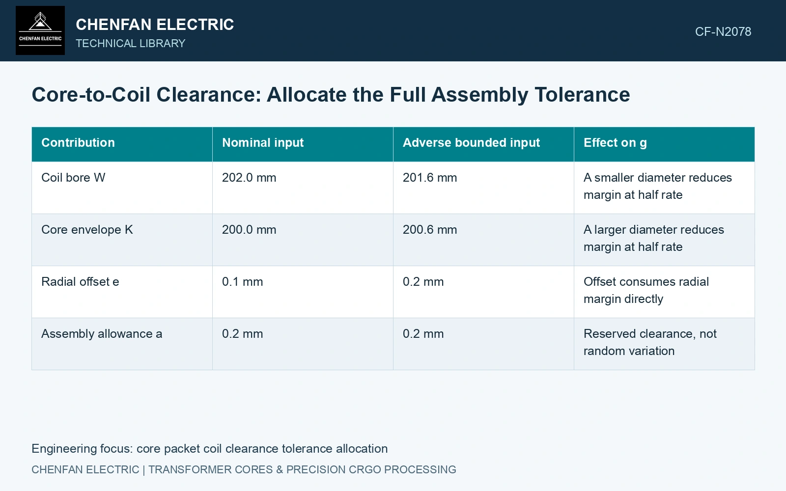
Assign every contribution a sign
The following dimensions are illustrative. They do not specify an acceptable transformer fit.
| Contribution | Nominal input | Adverse bounded input | Effect on g |
|---|---|---|---|
| Coil bore W | 202.0 mm | 201.6 mm | A smaller diameter reduces margin at half rate |
| Core envelope K | 200.0 mm | 200.6 mm | A larger diameter reduces margin at half rate |
| Radial offset e | 0.1 mm | 0.2 mm | Offset consumes radial margin directly |
| Assembly allowance a | 0.2 mm | 0.2 mm | Reserved clearance, not random variation |
The nominal residual is 0.7 mm. At the listed joint adverse bounds it becomes (201.6 − 200.6)/2 − 0.2 − 0.2 = 0.1 mm. This bounded calculation assumes that the extreme dimensions can coexist and that the circular model represents the limiting geometry.
Allocate tolerance where the process can deliver it
Compare the cost and capability of reducing packet spread, enlarging the bore target or improving alignment. Halving a bore tolerance may offer little value if an uncontrolled locating offset dominates the chain.
Packet measurement must use the specified compression state. Coil measurements should represent the relevant manufacturing and assembly condition. Add separate terms for shape, insulation protrusions or shoulders when they determine the passage; one diameter cannot absorb every local restriction.
Keep probabilities separate from drawing limits
For independent, locally linear variations with illustrative standard deviations u(W)=0.2 mm, u(K)=0.3 mm and u(e)=0.05 mm, the propagated standard deviation of g is √[(0.2/2)² + (0.3/2)² + 0.05²] = 0.187 mm. Correlated inputs require covariance terms with the signs from the chain. [1]
Estimating interference probability additionally requires credible joint distributions and their means. Under a justified normal model, the event g<0 can be evaluated from that distribution; bounded drawing tolerances alone do not supply it. Radial offset may itself be non-normal because it is a magnitude.
The catalogue 0.23 mm gauge makes a missing dimensional allocation tangible. [2] In the simplified circular fit, assume the core envelope diameter is set directly by a stack dimension and an extra lamination adds exactly one nominal gauge along that dimension. Starting from the adverse residual margin of 0.10 mm, the change is −0.23/2 = −0.115 mm, leaving −0.015 mm. That example changes the result from clearance to interference. Freeze the accepted sheet-count schedule and measured compressed envelope before approving insertion; a positive nominal margin cannot absorb an unallocated layer-count change.
Core envelope control includes sheet count, packet location, burr growth and compression. Coil-bore tolerance and axis offset remain separate allocations; do not spend the same assembly allowance on each independently.
Check the allocated budget on assembled examples and the limiting insertion path. Use gauges to verify that fit while maintaining achievable product and locating tolerances.
References
- B. N. Taylor and C. E. Kuyatt, NIST Technical Note 1297, Guidelines for Evaluating and Expressing the Uncertainty of NIST Measurement Results, 1994, sections 5 and 6.
- Nippon Steel Corporation, Grain-Oriented Electrical Steel Sheets, catalogue D004je, April 2020, specification and typical-property tables.