

A touch probe does not merely observe a thin lamination. It applies force. Near an unsupported end, that force can move the edge before the CMM records its position. Several repeat readings may agree because the same displacement occurs every time.
The relevant question is therefore how much of the measured coordinate belongs to the part’s original geometry and how much belongs to the measurement interaction. Instrument repeatability alone cannot answer it.
Start with the support span
For a simple elastic cantilever, tip deflection scales with F L³/(E I), where F is applied force, L is unsupported length, E is elastic modulus and I is the section’s second moment of area. This relationship explains why a small change in support span can matter greatly. It is not a calibrated correction for a coated lamination contacting neighboring sheets.
Observe whether the probe approaches an exposed sheet, several sheets together, or a solid supported stack. Contact direction matters too. A sheet may be stiff in its plane and compliant normal to it. A probe qualified on a rigid calibration sphere does not establish the flexibility of the production feature.
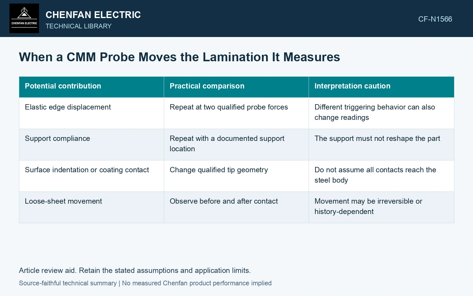
| Potential contribution | Practical comparison | Interpretation caution |
|---|---|---|
| Elastic edge displacement | Repeat at two qualified probe forces | Different triggering behavior can also change readings |
| Support compliance | Repeat with a documented support location | The support must not reshape the part |
| Surface indentation or coating contact | Change qualified tip geometry | Do not assume all contacts reach the steel body |
| Loose-sheet movement | Observe before and after contact | Movement may be irreversible or history-dependent |
Run a force comparison without changing the reference
Use the same datum, approach direction, point location and support arrangement. Verify that both force settings are valid for the probe system. Then measure enough repetitions to distinguish scatter from a systematic coordinate shift.
If coordinate x varies approximately as x = x₀ + kF over a demonstrated elastic range, x₀ is an extrapolated zero-force position and k is compliance in millimetres per newton. This model is an investigative tool. Two points alone do not establish linearity, and extrapolation through hysteresis or sheet slip is unjustified.
A qualified noncontact measurement can test whether the apparent shift follows the contact force. It has its own uncertainty from reflection, edge extraction and registration, so agreement should be assessed within both methods’ capabilities.
Where possible, move the contact onto a functionally relevant supported region. If the drawing controls the free projecting edge, however, measuring a convenient supported point does not verify that requirement. The measurement method must respect the feature being accepted.
If the edge changes position permanently during the comparison, stop treating the results as repeated observations of one unchanged part. Record the movement and investigate the restraint or stack condition. The correction is then mechanical stabilization or a suitable measurement method, rather than averaging more probe touches into a misleadingly precise coordinate.
Use sheet thickness to test probe-force sensitivity
Catalogue nominal thickness t = 0.23 mm [1] makes a thin free edge particularly compliant. Assume an isolated 10 mm wide cantilever, free length 20 mm, E = 200 GPa as a sensitivity assumption, and probe force 0.10 N. I = bt³/12 = 0.01014 mm⁴; δ = FL³/(3EI) = 0.1315 mm. Reducing free span to 10 mm gives 0.0164 mm at the same force. That eightfold difference can exceed an assumed 0.05 mm feature tolerance even with repeatable triggering. Validate the force/support model against a qualified noncontact observation before applying a correction; propagate thickness and force uncertainty [2].
Manufacturing controls. Sheet thickness, unsupported overhang, packet contact, restraint and approach direction control contact compliance. Moving support nearer the probe may help measurement, but the support must not reshape the free feature specified by the drawing.
References
- Nippon Steel Corporation, Grain-Oriented Electrical Steel Sheets, catalogue D004je_03_202004, 2020, Specifications; Size and Form Tolerances.
- JCGM, JCGM 100:2008, Evaluation of measurement data — Guide to the expression of uncertainty in measurement, 2008.