

A grounding drawing for a core assembly should identify electrical nodes, intentional connections, insulation boundaries and responsibility for verification. A ground symbol without those relationships is not enough. The drawing must also distinguish the normal service configuration from any separately authorized test configuration.
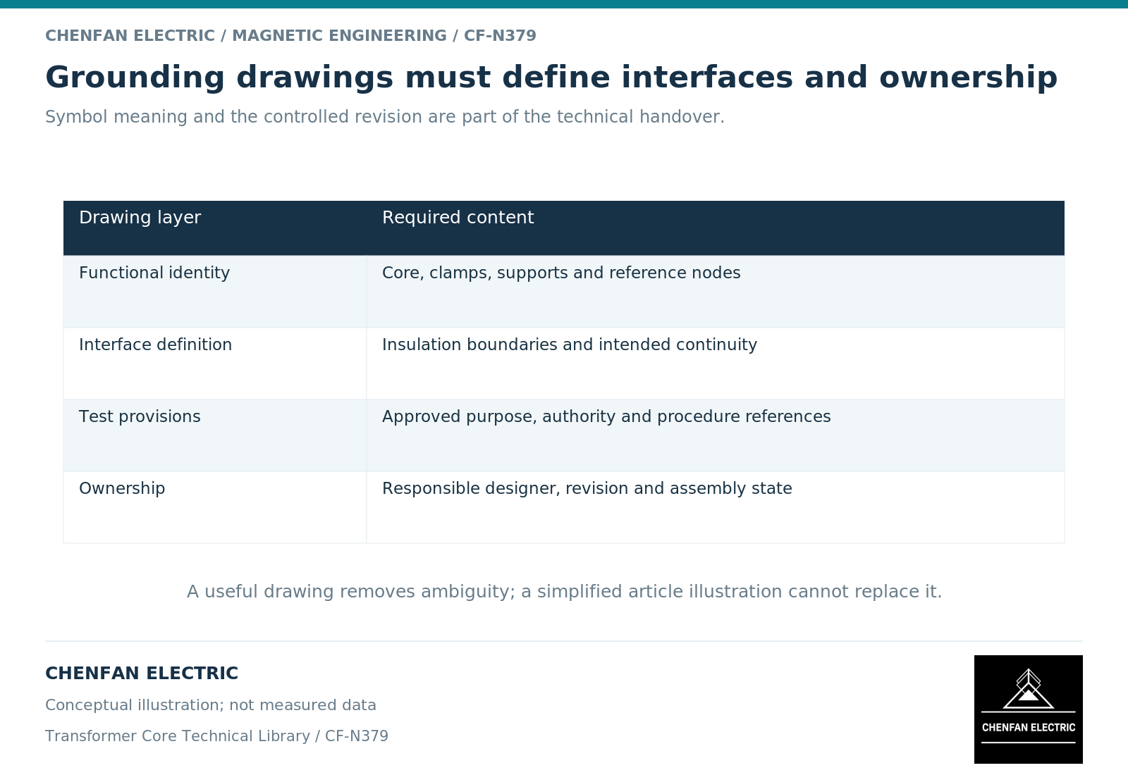
Give every significant node a physical identity
Name the core, clamps, tank, shields and relevant supports in a way that matches the mechanical drawings. Where sections are intentionally grouped, show that grouping explicitly. Where electrical separation is required, identify the interface rather than relying on the absence of a line.
The electrical network matters because potential control and ground-current behavior depend on the actual connected system. [1] A drawing should therefore communicate more than the location of the visible grounding terminal.
Use unambiguous labels and a legend. A dashed line might otherwise be interpreted as a shield, a mechanical relationship or an optional connection. The meaning must be established within the controlled drawing system.
Distinguish service links from test access
A test link or monitoring interface is not permission to change the grounding state during operation. Its function, permitted configurations and governing procedure should be identified by the responsible manufacturer.
The drawing can reference an approved test method without reproducing operational steps. Testing equipment documentation distinguishes different transformer electrical tests and their specific purposes. [2] A generic “test here” note does not define the object, safe state or acceptance criterion.
Avoid leaving a temporary test state visually indistinguishable from the released service state. Revision history and final configuration records should allow another reviewer to identify which arrangement was actually accepted.
Include an ownership matrix
| Interface item | Required owner or evidence |
|---|---|
| Intended electrical topology | Transformer design authority |
| Core-supplied insulation features | Defined core supply scope and drawing |
| Added clamps or lead supports | Active-part integration responsibility |
| Monitoring and test interfaces | Approved procedure and equipment definition |
| Final-state verification | Identified report and release authority |
Ownership should be explicit even when one company performs several functions. That prevents a component supplier’s inspection from being interpreted as approval of a later assembly it did not control.
A revision that moves a support or changes an insulating interface should identify its electrical consequence. Mechanical interchangeability does not necessarily imply electrical equivalence.
Make the drawing auditable without making it universal
The final record should tie node labels to physical part identifiers, drawing revisions and evidence references. An unresolved interface should remain visible as an engineering issue, not be concealed by adding a general grounding note.
A conceptual node map can support an early discussion, but it is not a construction drawing. It lacks equipment-specific dimensions, insulation coordination, safety controls and approved procedures. Do not circulate it as authority to add, remove or rearrange connections.
For an external core order, the useful handover extracts only the requirements that affect the supplied core and its interfaces, while preserving the transformer’s overall grounding authority. The result is a clear division of work: the supplier manufactures to a defined electrical boundary, the integrator maintains that boundary, and the responsible reviewer verifies the final system.
References
[1] Xiu Zhou and coauthors / Frontiers in Energy Research. Analytical modeling and calculation of core grounding current in converter transformer (2023).
[2] OMICRON. Common Electrical Tests on Power Transformers.