

A bore-like insertion gauge is useful only when its relationship to the real winding is defined. A gauge that is slightly larger than intended may pass a core that the smallest allowed winding bore cannot clear. A smaller gauge may reject a core that would fit safely.
The gauge therefore belongs in the tolerance allocation. Its size variation, shape, wear and locating behavior consume part of the difference between the allowed core envelope and the available winding bore.
Identify the acceptance direction
For a simple circular fit, let Wmin be the minimum permitted winding bore and Kmax the maximum permitted core envelope, both diametral millimetres. The available geometric difference is Wmin − Kmax before assembly allowances and uncertainties are considered.
Let G be the gauge bore. Passing means that the tested core can traverse that gauge under the specified motion. If G grows through wear, passage becomes easier. That is the false-acceptance direction for this bore-like arrangement. Other gauge designs may have different wear directions and must be analyzed separately.
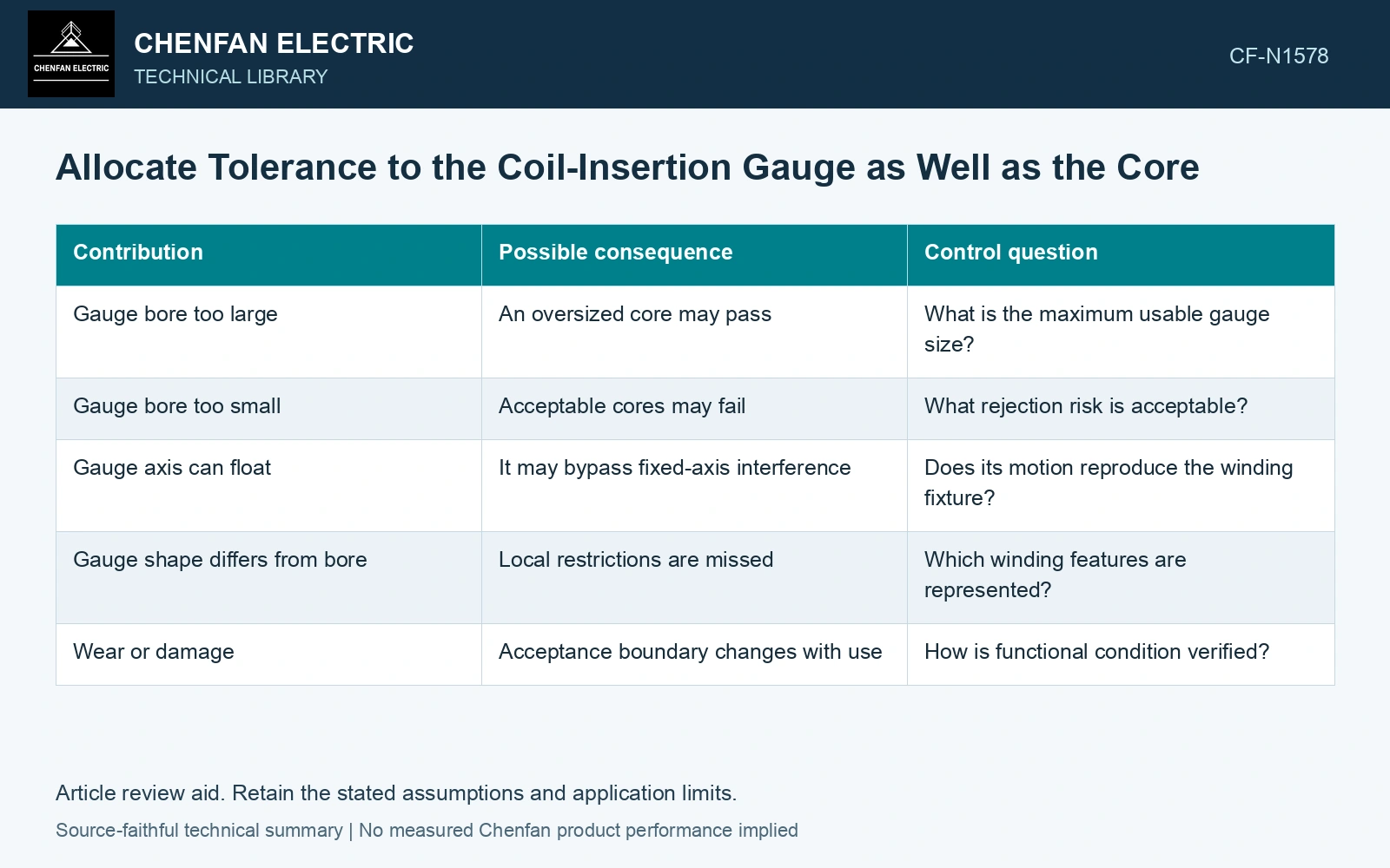
| Contribution | Possible consequence | Control question |
|---|---|---|
| Gauge bore too large | An oversized core may pass | What is the maximum usable gauge size? |
| Gauge bore too small | Acceptable cores may fail | What rejection risk is acceptable? |
| Gauge axis can float | It may bypass fixed-axis interference | Does its motion reproduce the winding fixture? |
| Gauge shape differs from bore | Local restrictions are missed | Which winding features are represented? |
| Wear or damage | Acceptance boundary changes with use | How is functional condition verified? |
Allocate the available margin deliberately
Do not simply set the gauge to the winding’s nominal bore. Start with the limiting winding geometry, the intended core limit and the necessary assembly allowance. Then assign a defensible range for gauge manufacturing and use, considering uncertainty in its verification.
The guard band between an acceptance decision and a product limit depends on the agreed decision rule and measurement risk. No universal fraction of the product tolerance resolves every gauge task. The uncertainty must reflect the actual gauge geometry and use conditions.
For a family of winding designs, identify which model has the limiting restriction at each part of the travel. One smallest nominal diameter may not represent a shoulder or a noncircular region on another model. A universal gauge needs a documented functional envelope, not a list of products assumed equivalent.
Record passage conditions: orientation, locating references and permitted motion. Increasing force until the gauge passes changes the meaning of the test and may move sheets or damage insulation interfaces.
Verify the gauge at an interval justified by its wear and handling, and after damage that can change function. A passing result should be associated with a gauge known to be within its usable boundary at that time. Otherwise the result describes an unknown bore, which offers little assurance about the actual winding fit.
Budget a gauge around the catalogue width range
The catalogue permits 0/−0.3 mm width tolerance for 0.23 mm stock in the 150–400 mm width band [1]. Assume a 300.0 mm nominal strip controls one envelope direction, an assembled envelope limit of 300.40 mm, a 301.00 mm minimum bore, a 0.30 mm required diametral assembly allowance, and gauge expanded uncertainty of 0.05 mm. The functional bore boundary is 301.00 − 0.30 = 300.70 mm, but the stricter core-envelope limit sets the effective gauge maximum at 300.40 mm. A measured bore of 300.35 mm reaches that boundary after adding uncertainty; a 300.45 mm gauge reaches 300.50 mm and is too permissive. The 299.70–300.00 mm stock range cannot substitute for the assembled-envelope requirement [2].
Manufacturing controls. Slitting width, packet build, protruding sheets and axis alignment consume fit margin. Gauge wear and axis freedom are separate controls. Tie the gauge to the approved winding restriction rather than to a nominal cut width.
References
- Nippon Steel Corporation, Grain-Oriented Electrical Steel Sheets, catalogue D004je_03_202004, 2020, Specifications; Size and Form Tolerances.
- JCGM, JCGM 100:2008, Evaluation of measurement data — Guide to the expression of uncertainty in measurement, 2008.