

A model that deletes a bonded interface when a stress exceeds adhesive strength can predict crack initiation without describing crack growth correctly. Propagation consumes energy over a separation process. That distinction matters when only part of a transformer packet has lost its bond.
A cohesive interface represents traction as a function of relative separation. Its use is justified only if the selected law, material state and loading modes connect to the joint being modeled. The law is an engineering representation; it is not a direct measurement of every microscopic event.
Separate the beginning from the growth
Let traction T be in pascals and separation delta in metres. The area under a traction-separation curve has units of joules per square metre. This fracture-energy quantity describes the energy associated with creating unit area of separated interface in the modeled mode.
The peak traction influences initiation. The post-peak curve and its area influence propagation. Two laws with the same peak can have different energies and therefore different crack-growth responses. Fitting only a maximum coupon force cannot identify both uniquely.
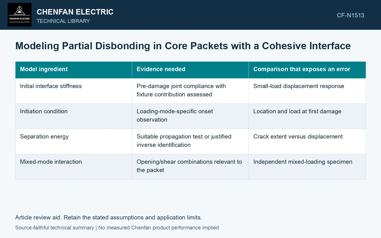
| Model ingredient | Evidence needed | Comparison that exposes an error |
|---|---|---|
| Initial interface stiffness | Pre-damage joint compliance with fixture contribution assessed | Small-load displacement response |
| Initiation condition | Loading-mode-specific onset observation | Location and load at first damage |
| Separation energy | Suitable propagation test or justified inverse identification | Crack extent versus displacement |
| Mixed-mode interaction | Opening/shear combinations relevant to the packet | Independent mixed-loading specimen |
If an input is unavailable, define the model as a sensitivity study. Do not label an assumed interface law a measured material property.
Model the actual failure plane
A bonded lamination may fail within adhesive, at adhesive/coating contact, or at the original coating/steel interface. Assigning the cohesive law to the wrong plane can give a useful fit to one load curve while predicting the wrong mechanism elsewhere.
Use paired fracture-face observations to identify the interface represented. Keep adhesive thickness and substrate deformation in the model consistent with the specimen. Otherwise excessive compliance in one part can be compensated by an unrealistic parameter in another.
Demonstrate numerical stability
Repeat the calculation with a refined interface mesh and suitable time or displacement increments. Compare onset, propagation and dissipated energy, not only the final reaction force. Check that the regularization or process-zone representation does not create a mesh-dependent amount of energy loss.
Contact after separation also needs explicit treatment. A disbonded region may close and carry compression or friction without regaining its adhesive bond. Allowing it to transmit tensile traction again without a justified healing model changes the physical question.
Verify the model against a load history or geometry not used to fit its parameters. For the packet application, examine whether predicted local opening, slip and crack extent remain consistent with measured observations. A calibrated coupon law can support an investigation of partial disbonding; it becomes a predictive packet tool only after that transfer has been tested.
Technical references
- voestalpine. Backlack: Lamination bonding.
- voestalpine. Backlack: Testing methods and production of test specimens.
- COMSOL official documentation. Decohesion.
- COMSOL. How to Model Adhesion and Decohesion in COMSOL Multiphysics.