

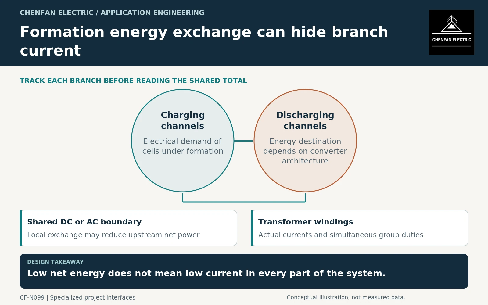
Battery-formation equipment can charge and discharge cells in coordinated cycles, but the transformer duty depends on where energy is exchanged. Some conversion architectures can reuse energy locally or return it upstream; others handle it differently. Specify group schedules and actual winding currents rather than assuming that low net plant energy means low transformer duty.
Identify the regeneration path
Draw the formation channels, converter groups, any shared direct current (DC) link and the alternating current (AC) supply boundary. Ask the equipment supplier which discharge energy reaches the AC network, which is reused locally and which is dissipated.
Converter-transformer application guidance addresses specialized conversion interfaces within its scope. It does not establish the architecture or efficiency of a particular formation line. [1]
Do not describe all formation equipment as inherently regenerative. The actual capability, enabled modes and operating limits must be supported by the purchased system’s documentation.
Separate channel behavior from transformer input
Cell-level current and voltage are not the same quantities as transformer winding current. The conversion stages, channel aggregation, losses and auxiliaries intervene between them.
In an illustrative loss-free common-AC-bus case, 2 MW of charging demand and 1.5 MW of returned discharge power produce 0.5 MW of net active import. That arithmetic does not establish transformer apparent power or individual branch current. It also does not describe a multiwinding transformer automatically.
Where groups connect to separate windings, each winding retains its own duty even if net power at another boundary is small. General transformer application guidance supports reviewing connections and winding operating conditions. [2]
The specification should identify P-Q behavior, root-mean-square current and waveform evidence at each relevant transformer boundary. A plant energy meter alone cannot provide all of that information.
Preserve the group schedule and failure states
| Formation state | Required interface question |
|---|---|
| Coordinated charging and discharge | Where is energy exchanged? |
| Predominantly charging groups | What maximum import duty occurs? |
| Predominantly discharging groups | Is upstream export supported and permitted? |
| One group unavailable | Does the assumed local balancing disappear? |
| Schedule or controller failure | What current limits remain enforced? |
A capacity reduction based on synchronized cycles is an operating assumption. If production changes or a group outage destroys the assumed balance, the transformer duty must remain bounded by implemented limits or be reassessed.
Harmonic evidence should cover relevant converter modes and aggregation assumptions. ABB’s harmonic guidance supports treating nonlinear-load behavior as a system issue rather than a single brochure percentage. [3]
Define the purchasing and acceptance boundary
The enquiry should include the converter architecture, winding arrangement, group duty matrix, current spectra and chronological production schedule. Ask the supplier to state which sharing assumptions its transformer assessment uses.
Where the arrangement is a specialized industrial converter transformer, select the applicable IEC 61378 framework rather than using a generic distribution label. [4] Evidence should distinguish transformer characteristics from complete formation-line performance.
Acceptance should verify that the implemented production scheduling and controls preserve the assessed operating envelope. Adding channels, changing formation recipes or enabling a new regeneration mode can alter duty without a proportional change in annual energy consumption.
The useful specification follows current through the actual conversion architecture. Net energy savings may be commercially important, but they cannot replace winding-level data or prove that every component experiences a small electrical load during coordinated battery cycling.
Core procurement checkpoint: Identify the formation-equipment conversion boundary
Battery-formation equipment can exchange energy internally or with a common bus, but the core supplier needs the transformer’s own approved electrical and mechanical design. Net plant energy does not establish individual winding duty or core geometry. State the converter arrangement and excitation basis used by the designer, and keep complete-equipment harmonic, thermal and regeneration assessment outside the material supply claim.
For the core enquiry: Converter/transformer location; approved core drawing; waveform assumptions; steel specification; inspection boundary and equipment-design owner.