

The tertiary voltage follows its linked magnetic excitation and turns. A regulating operation can change that excitation even when the main controlled terminal reaches its setpoint. Derive the relationship from the circuit rather than assuming a constant tertiary nameplate voltage at every tap.
For an ideal common-flux arrangement, let the high terminal energize total turns NH and the tertiary have NT turns. Neglect winding drops and assume corresponding polarity. Then VT = VHNT/NH.
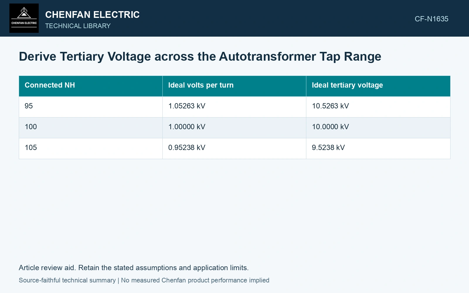
A fixed-high-voltage example
Use illustrative VH = 100 kV and NT = 10 turns. If the connected high-side turns change, the tertiary voltage changes as follows. All numerical inputs and limits in the illustrative cases are assumptions unless a catalogue or standard source is explicitly identified.
| Connected NH | Ideal volts per turn | Ideal tertiary voltage |
|---|---|---|
| 95 | 1.05263 kV | 10.5263 kV |
| 100 | 1.00000 kV | 10.0000 kV |
| 105 | 0.95238 kV | 9.5238 kV |
These values demonstrate the ratio and are not a practical tap design. The tertiary varies because the fixed applied voltage is distributed over different energized turns.
If a regulating scheme preserves the main-core volts per turn while injecting a separate voltage to the controlled terminal, the tertiary relationship can be different. A side-limb or auxiliary scheme needs its own magnetic and circuit model; its behavior cannot be inferred from the table above.
Include the tertiary’s own configuration
Record tertiary turn selection, phase connection and any separate taps. A line-to-line tertiary voltage may include a connection factor relative to the per-phase induced voltage. Keep that conversion consistent across the schedule. Keep connection, tapping and network assumptions explicit in the application assessment [1].
| Schedule field | Reason |
|---|---|
| Actual regulating connection | Defines which magnetic voltage changes |
| Selected main and tertiary turns | Supports the ideal ratio derivation |
| Fixed source or controlled voltage | Identifies the operating assumption |
| Loaded tertiary current and power factor | Supports voltage-drop assessment |
| Required auxiliary voltage window | Provides the functional comparison |
Under load, include the relevant resistance and leakage effects. An ideal no-load ratio table does not establish the minimum voltage at an auxiliary load. Simultaneous main-port duty can also change internal currents and drops.
Find the limiting combination
Evaluate all relevant taps and tertiary loads within the actual operating assumptions. The minimum auxiliary voltage may occur at a different condition from the maximum tertiary current. Keep both with their cooling and source-voltage premises.
Compare the derived schedule with qualified ratio and voltage evidence. If the measured pattern differs, inspect tap selection, phase conversion and the fixed-voltage assumption before attributing it to the tertiary. Assess the relevant measured quantities with a defined measurement model and propagated uncertainty [2].
Issue a three-port voltage schedule for the tap and load states covered by the regulation model. Compare the auxiliary-supply window with that schedule, including the states where terminal voltage differs from the nominal tertiary value.
Compare the tertiary schedule with an auxiliary window
The turn counts in the ratio table are deliberately normalized assumptions. Its tertiary voltages are 100×10/95 = 10.5263 kV, 100×10/100 = 10.0000 kV and 100×10/105 = 9.5238 kV RMS. Assume a 50 Hz auxiliary supply window of 9.8–10.2 kV RMS. Only the middle no-load tap lies within that window; the other two already fail before loaded voltage drop is included. The required decision is to revise the supply arrangement or its permitted tap range and then calculate loaded voltage, rather than approve every position from the nominal 10 kV value. Record rated quantities and test conditions on the general power-transformer basis of IEC 60076-1 [3].
References
- IEC, IEC 60076-8:1997, Power transformers – Part 8: Application guide, 1997, official public scope.
- JCGM, JCGM 100:2008, Evaluation of measurement data — Guide to the expression of uncertainty in measurement, 2008.
- IEC, IEC 60076-1:2011, Power transformers – Part 1: General.