

A fault supplied from both voltage systems produces one internal current pattern. Removing a source changes the network and can change that pattern’s directions and relative magnitudes. Comparing only the total bus fault current can miss the winding that becomes limiting. Record rated quantities and test conditions on the general power-transformer basis of IEC 60076-1 [1].
Define the fault location and type, the connected sources and their impedances. Solve each approved system state separately. Keep current arrows fixed across the comparisons so that a change of direction remains visible.
Map each state into winding currents
For a simple connection with IH entering the high terminal and IL leaving the low terminal, series current is IH and common current is IH − IL. Additional tertiary or regulating duties require their full connection model.
The common-current magnitude depends on relative phase and direction. A decrease in one terminal contribution can remove a cancellation in the vector difference. Therefore a decrease in total fault contribution does not mathematically require every branch magnitude to decrease.
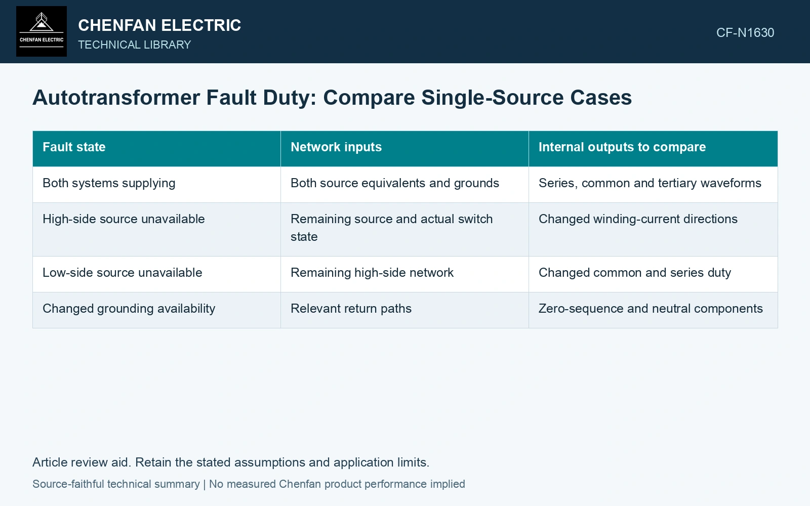
| Fault state | Network inputs | Internal outputs to compare |
|---|---|---|
| Both systems supplying | Both source equivalents and grounds | Series, common and tertiary waveforms |
| High-side source unavailable | Remaining source and actual switch state | Changed winding-current directions |
| Low-side source unavailable | Remaining high-side network | Changed common and series duty |
| Changed grounding availability | Relevant return paths | Zero-sequence and neutral components |
These rows organize the study; they do not establish that every installation permits every listed state. Use the actual switching and grounding configurations.
Carry the waveform into mechanical assessment
RMS current supports part of a thermal comparison. Electromagnetic force depends on the current and field histories, including asymmetrical components where relevant. Do not assign force by scaling a bus-current magnitude while leaving the internal distribution unchanged.
Compute group or section forces using the corresponding load case and trace their reactions through the actual supports. A changed common-current direction can alter local field relationships even if one terminal RMS value is similar.
Check continuous and short-time thermal boundaries separately. A fault-duration assumption belongs with the current duty, while peak mechanical response requires its own dynamic or approved equivalent treatment.
Identify the limiting state explicitly
Tabulate maximum relevant current, force or energy measure by winding and network state. Different outputs can have different limiting states. Avoid selecting a single “worst fault” solely from the largest external current.
Verify current and power or energy consistency appropriate to the model before interpreting the results. Missing source or neutral branches can create a misleadingly low calculated duty. Assess the relevant measured quantities with a defined measurement model and propagated uncertainty [2].
Identify the internal section and duty that limit each single-source fault case. Retain that result alongside the bus fault current so that loss of a source does not conceal a more demanding internal distribution.
Compare the limiting internal current, not only the bus sum
For a KCL sensitivity illustration, assume 50 Hz current phasors referenced by the arrows above. In the first trial pair, IH = 8 kA and IL = 10 kA, giving IC = −2 kA. In the second trial pair, IH = 0 kA and IL = 6 kA, giving IC = −6 kA. Low-port current falls by 40%, while common-section current triples. For equal fault duration and resistance its I²t contribution rises by a factor of 9. These trial pairs demonstrate only the current-difference sensitivity. Establish any feasible operating state by solving the complete fault network, including tertiary and magnetic balance, before assigning winding duty. Keep connection, tapping and network assumptions explicit in the application assessment [3].
References
- IEC, IEC 60076-1:2011, Power transformers – Part 1: General.
- JCGM, JCGM 100:2008, Evaluation of measurement data — Guide to the expression of uncertainty in measurement, 2008.
- IEC, IEC 60076-8:1997, Power transformers – Part 8: Application guide, 1997, official public scope.