

A multiport autotransformer can receive power at two terminals and deliver it at another. Its net power balance may look ordinary while its internal current pattern differs from the familiar high-to-low transfer.
Define all terminal currents as entering the equipment for complex-power accounting, so ΣVkIk* equals losses under the appropriate steady-state model. Then convert those terminal references into the arrows used for each winding branch. Mixing the two conventions can create a false cancellation.
Compare power closure and current duty separately
For the illustrative ideal connection with NC = 80, NS = 20 and NT = 10 turns, use IH entering H, IL leaving L and IT entering the dotted tertiary. The internal equations are IH = 0.8IL − 0.1IT and IC = IH − IL.
At ideal aligned voltages of 100, 80 and 10 kV, take IL = 100 − j50 A and IT = 100 + j200 A. The current map gives IH = 70 − j60 A and IC = −30 − j10 A. The common-section RMS magnitude is about 31.6 A.
Using S = VI*, high-side input is 7 + j6 MVA and tertiary input is 1 − j2 MVA. Together they supply 8 + j4 MVA at L. Real and reactive power both close, but the closure does not identify the current in any conductor. Reporting only 7, 1 and 8 MW would omit the reactive exchange that changes those currents.
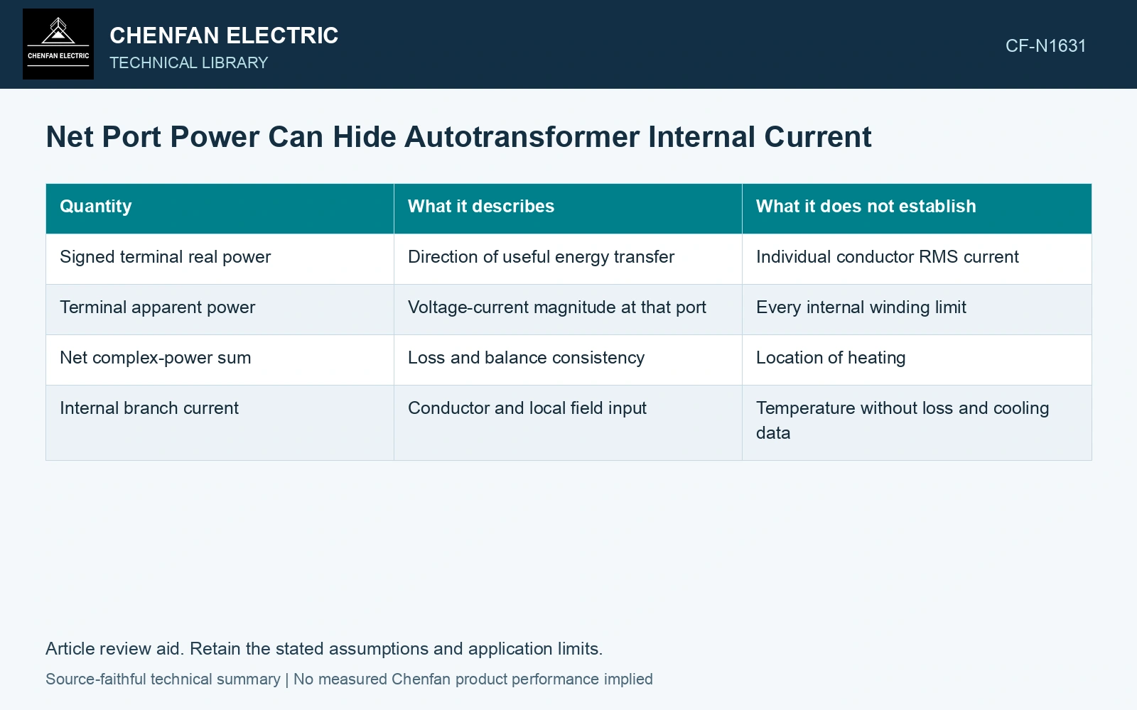
| Quantity | What it describes | What it does not establish |
|---|---|---|
| Signed terminal real power | Direction of useful energy transfer | Individual conductor RMS current |
| Terminal apparent power | Voltage-current magnitude at that port | Every internal winding limit |
| Net complex-power sum | Loss and balance consistency | Location of heating |
| Internal branch current | Conductor and local field input | Temperature without loss and cooling data |
The values are illustrative single-phase circuit arithmetic, not equipment capability. The phasors satisfy this ideal connection; they do not establish an available dispatch state or a permitted current limit for a real unit. All numerical inputs and limits in the illustrative cases are assumptions unless a catalogue or standard source is explicitly identified.
Include reactive circulation
Two ports can exchange reactive power with small net real transfer. Their currents still contribute to winding losses and electromagnetic loading. A dispatch study based only on active power can therefore omit a demanding internal state.
Use the actual voltage relationships and network solution to determine feasible port phasors. Arbitrarily selected current angles may satisfy one node equation while violating the rest of the transformer or system model. Keep connection, tapping and network assumptions explicit in the application assessment [1].
Compare the mapped currents against tap-specific winding and cooling limits. Evaluate relevant harmonics separately when the load is nonsinusoidal; fundamental power does not determine total RMS current.
Record the complex power at every port together with the corresponding internal winding currents. Use those currents to assess conductor duty; a small net port flow can coexist with substantial internal current in the combined operating state.
Use the phasor result as the conductor check
All turn counts, voltages and currents in this article’s numerical example are assumptions for a 50 Hz single-phase circuit. Python evaluation of the stated map gives |IH| = 92.20 A and |IC| = 31.62 A. An assumed common-section limit of 30 A is exceeded by 5.4%, although real-power balance is exact: 7 + 1 = 8 MW. Reactive balance is also exact: 6 − 2 = 4 MVAr. Retain both closures as checks on signs, then reject this operating point on the assumed internal current limit. Power closure is a consistency check, not proof of thermal capability [2]. Record rated quantities and test conditions on the general power-transformer basis of IEC 60076-1 [2]. Assess the relevant measured quantities with a defined measurement model and propagated uncertainty [3].
References
- IEC, IEC 60076-8:1997, Power transformers – Part 8: Application guide, 1997, official public scope.
- IEC, IEC 60076-1:2011, Power transformers – Part 1: General.
- JCGM, JCGM 100:2008, Evaluation of measurement data — Guide to the expression of uncertainty in measurement, 2008.