

An artificial fault is valuable when it makes a research variable controllable. That controllability does not make it identical to a burr, coating scratch or movable debris contact in a production core. The artificial specimen may have a different contact resistance, return path, linked flux and heat-transfer boundary.
Define the mechanism that the specimen is intended to represent before using it to calibrate detection. A trial designed to evaluate surface thermography may not represent the electrical behavior needed for a current-path model.
Separate contact from loop geometry
Contact construction determines electrical behavior at the bridge, including its dependence on load and temperature. Loop geometry determines the magnetic flux linked by the conductive path. Changing both together makes a heating trend difficult to interpret.
Use a professional laboratory plan that can vary one relevant factor while preserving the other where feasible. The physical preparation and excitation procedure requires responsible test engineering; it should not be improvised on an operating or deliverable core.
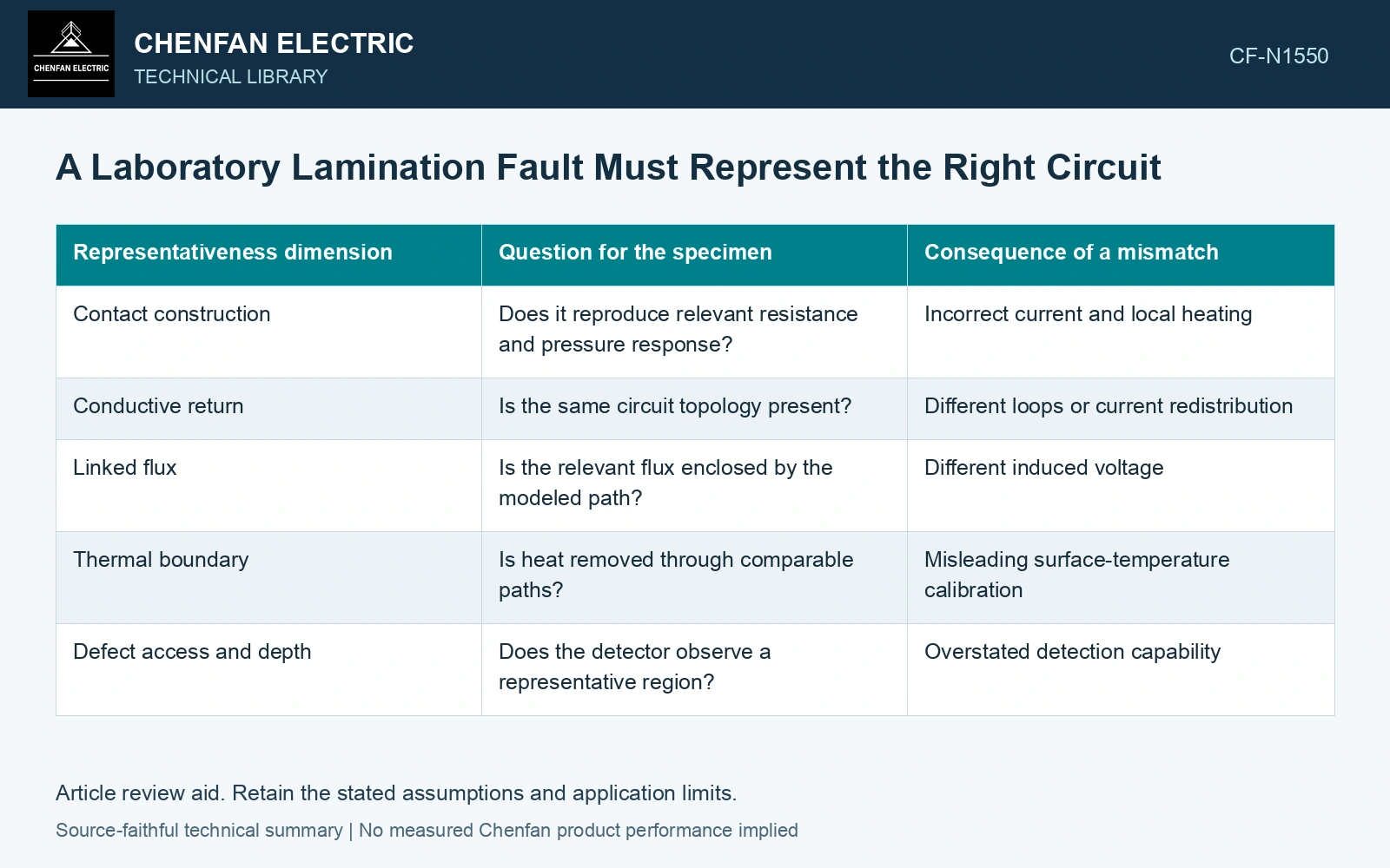
| Representativeness dimension | Question for the specimen | Consequence of a mismatch |
|---|---|---|
| Contact construction | Does it reproduce relevant resistance and pressure response? | Incorrect current and local heating |
| Conductive return | Is the same circuit topology present? | Different loops or current redistribution |
| Linked flux | Is the relevant flux enclosed by the modeled path? | Different induced voltage |
| Thermal boundary | Is heat removed through comparable paths? | Misleading surface-temperature calibration |
| Defect access and depth | Does the detector observe a representative region? | Overstated detection capability |
These questions should be answered independently. A good match in visible defect area cannot compensate for a different electrical return.
Keep real-damage evidence separate
A genuine damaged sample can provide useful morphology and contact-history information. Its geometry may be difficult to control, and dismantling may change its state. Record those limitations instead of treating it as either a perfect reference or an unusable anomaly.
Compare artificial and real features through the response relevant to the study, with uncertainty and boundary conditions stated. Similar temperature maxima alone do not prove equivalent circuits. Conversely, different maxima can result from cooling differences even when a contact mechanism is similar.
Report what the specimen validates
State whether the experiment validates a thermal observation method, an electromagnetic response, a contact model or a combination. Preserve the known specimen inputs and raw outputs. Avoid assigning every fault class the severity of the easiest laboratory defect to construct.
If a detection method succeeds on a conspicuous surface bridge, further trials are needed before claiming sensitivity to deep, intermittent or weak-contact defects. The qualification domain should grow through demonstrated comparisons.
The specimen’s useful contribution is a controlled test of a defined mechanism. A representativeness matrix keeps that contribution clear and prevents a repeatable artificial fault from becoming unsupported proof that the same detector finds every defect in a finished transformer core.
Match linked area before comparing artificial contacts
The catalogue nominal sheet thickness is 0.23 mm [1]. Assume a representative loop spans 10 sheet thicknesses and 100 mm length, while a laboratory loop spans 20 sheet thicknesses over the same length. Areas are 230 and 460 mm². With assumed uniform normal flux of 1.0 T peak at 50 Hz and equal 0.10 Ω purely resistive loops, induced rms voltages are 0.0511 and 0.1022 V; heating is 0.0261 and 0.1044 W. Doubling layer separation quadruples heating without changing contact resistance. Match linked area or normalize through a validated circuit before claiming the specimen reproduces the target fault; preserve geometry and resistance uncertainty [2]. Faraday induction supplies the voltage relation [3]. The assumed field is normal to this loop; main rolling-direction flux is not automatically linked.
Manufacturing controls. Layer count, loop length, coating damage, bridge pressure and cooling contact control representativeness. Validate detector coverage and contact behavior separately; an easily heated exposed bridge does not establish sensitivity to buried intermittent contacts.
References
- Nippon Steel Corporation, Grain-Oriented Electrical Steel Sheets, catalogue D004je_03_202004, 2020, Specifications; Size and Form Tolerances.
- JCGM, JCGM 100:2008, Evaluation of measurement data — Guide to the expression of uncertainty in measurement, 2008.
- Zhao, X. et al., Magnetostrictive Properties of the Grain-Oriented Silicon Steel Sheet under DC-Biased and Multisinusoidal Magnetizations, Materials 12, 2156, 2019, sections 2.1 and 2.3; DOI: 10.3390/ma12132156.