

An insulating tie-rod connection has distinct root, external-thread and nut failure paths. Test the complete rod, nut and seating arrangement to select engagement against the mechanism that actually limits it.
Calculation basis. Project-specific values and gates in the illustrative screens below are assumptions; cited catalogue values retain their source test conditions.
Identify both materials and constructions. A laminated-pressboard rod, a glass-reinforced rod and their mating nuts are not equivalent connections. Their threading routes and material directions can change the damage produced at the tooth and root. IEC 61212-1 defines material designations for specified resin-laminated rods and tubes [1]; a plain pressboard construction needs its own applicable material basis.
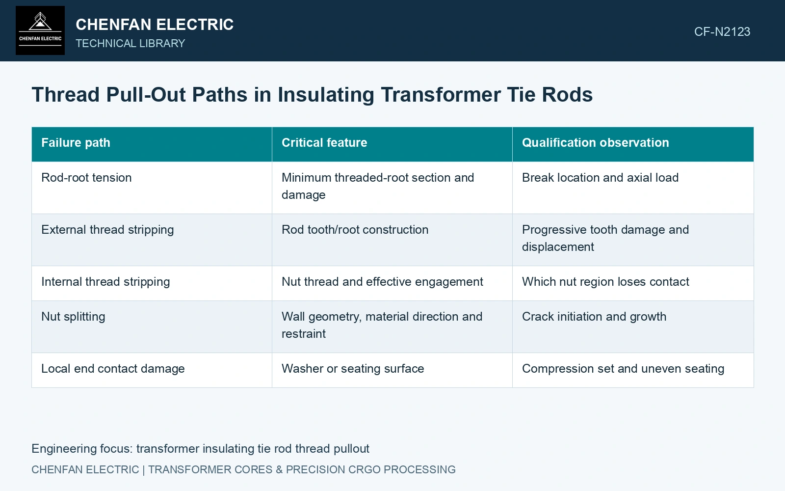
Follow the force through the connection
| Failure path | Critical feature | Qualification observation |
|---|---|---|
| Rod-root tension | Minimum threaded-root section and damage | Break location and axial load |
| External thread stripping | Rod tooth/root construction | Progressive tooth damage and displacement |
| Internal thread stripping | Nut thread and effective engagement | Which nut region loses contact |
| Nut splitting | Wall geometry, material direction and restraint | Crack initiation and growth |
| Local end contact damage | Washer or seating surface | Compression set and uneven seating |
For an illustrative rod carrying 6 kN through a 10 mm minimum root diameter, the nominal axial stress is 6000/[π(10²)/4] = 76.394 MPa. This does not include the local thread-root concentration and is not an allowable stress.
An illustrative 20 mm nominal engagement with 2 mm pitch contains ten pitches. It does not establish ten equally loaded threads. Chamfers, incomplete threads and deformation can reduce the effective engagement, and the force distribution needs assessment.
Test rod and nut together
Use representative threaded parts rather than smooth tensile coupons alone. Match thread profile, manufacturing route, engagement, nut geometry and the relevant oil and temperature state. Record displacement as well as maximum load so progressive stripping is distinguishable from a sudden root break.
Include post-test examination of both members. A connection that remains together can still develop damaged teeth or a crack in the nut. Qualification sections should reveal whether machining interrupted reinforcement or separated layers in the critical regions.
Generic metal fastener manuals distinguish root tension and thread pullout, but their empirical strength formulas do not supply an insulating-material capacity. The same limitation applies to tightening tables: metal thread friction, allowable preload and installation damage cannot be assumed for this connection.
Where the joint is tightened to create preload, qualify the installation method separately from the axial pull test. A rod that survives direct tension may be damaged by combined torsion and tension during assembly. Oil exposure can also change contact behaviour and must be represented where relevant.
Choose engagement from the observed limiting path. When added length shifts failure to the rod root, address that root and preserve the tested rod, nut and seating configuration.
Locate the capacity crossover before adding engagement
Root tension and thread pullout are separate paths [2]. Assume, solely for a planning comparison, a 10 kN rod-root capacity and a linear pullout-capacity hypothesis of 0.40 kN per millimetre of engagement. These are invented component inputs, not material strengths or test results.
At 20 mm engagement, pullout capacity is 8 kN and combined capacity is min(10,8) = 8 kN. At 30 mm it is min(10,12) = 10 kN, now root-controlled. Engagement grows 50% but combined capacity grows only 25%. An assumed 11 kN component requirement fails both; further engagement cannot overcome the assumed 10 kN root limit.
Obtain representative rod/nut evidence for root concentration, actual thread sharing, nut splitting and conditioned construction before selecting engagement. Do not import a metal-thread empirical allowable into the insulating connection.
References
- IEC, IEC 61212-1:2006, Insulating materials — Industrial rigid round laminated tubes and rods based on thermosetting resins for electrical purposes — Part 1: Definitions, designations and general requirements.
- R. T. Barrett, Fastener Design Manual, NASA Reference Publication 1228, 1990.