

Assume two windows, 600 mm high × 200 mm wide and 400 mm × 300 mm: both have area 120,000 mm². Also assume the installed coil/insulation envelope requires 500 mm height and 220 mm width. The first fails width; the second fails height. A 550 mm × 240 mm candidate passes this rectangular screen, pending the actual insertion path. Optimizing area alone misses both exclusions.
Use window height and width as separate coordinates. The candidate region should be cut by constraints from the intended winding arrangement, with the physical meaning of each boundary retained.
Draw the manufacturing boundaries first
Specify the axial winding build, end insulation, supports and any lead exits occupying the window height. In the width direction, include the complete radial coil build and the required clearances between coils and limbs. Use the chosen reference surfaces; a distance from bare steel cannot replace a distance from the final insulation surface.
Winding-tool limits may restrict coil diameter, height, conductor bend radius or handling posture. The finished coil also needs an insertion path. An opening that accommodates the final section can still be unusable if the coil cannot pass a yoke feature or if a lifting attachment has no clearance.
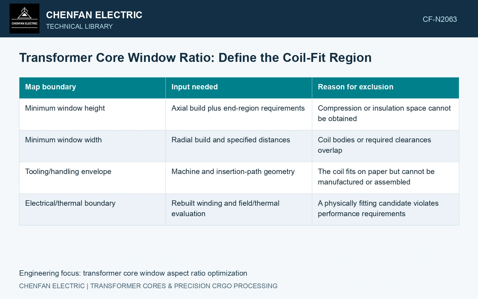
| Map boundary | Input needed | Reason for exclusion |
|---|---|---|
| Minimum window height | Axial build plus end-region requirements | Compression or insulation space cannot be obtained |
| Minimum window width | Radial build and specified distances | Coil bodies or required clearances overlap |
| Tooling/handling envelope | Machine and insertion-path geometry | The coil fits on paper but cannot be manufactured or assembled |
| Electrical/thermal boundary | Rebuilt winding and field/thermal evaluation | A physically fitting candidate violates performance requirements |
Rebuild the coil at each surviving point
A taller, narrower window can change the axial turns distribution, while a shorter one may require more radial layers or discs. Preserve required turns and conductor duty. Rebuild mean turn length and resistance when geometry changes; DOE’s transformer model links winding current and copper loss [1].
Leakage reactance depends on the winding positions and leakage-field paths, not solely on the rectangle’s aspect ratio. Recalculate it using a method validated for the resulting construction. The same geometry change can alter eddy losses, cooling channels and short-circuit forces; passing a leakage target does not close those other checks.
Make the feasible region visible
On the height–width map, mark manufacturing and assembly exclusions separately from performance exclusions. Plot mass, loss or cost contours only over points that have passed the geometry screen. Label discontinuities where a layer, disc or tooling choice changes, since a smooth search may otherwise interpolate through a nonexistent coil arrangement.
Use the catalogue density, 7,650 kg/m³, when the window change also moves the steel path. [2] Assume a mean magnetic path of 2.0 m and net section 0.010 m²: straight-path steel is 153 kg. If the taller window adds an assumed 0.20 m to that path while preserving section, mass rises by 15.3 kg. The equal 120,000 mm² windows therefore need not have equal steel cost, resistance or insertion feasibility. Under an assumed 3 currency units/kg, this path change alone adds 45.9 currency units. Compare it with the rebuilt coil and actual manufacturing clearances, rather than selecting solely on window area.
Available widths, packet schedule and yoke closure procedure establish the actual window and insertion path. Include compressed coil dimensions and tooling clearance before releasing a continuous height–width optimum.
Deliver a reconstructible winding layout and insertion check at the limiting dimensions. Allocate real coil-process variation and assembly allowance alongside the material estimate used to select the window.
References
- U.S. Department of Energy, DOE-HDBK-1011/4-92, Electrical Science, Volume 4, 1992.
- Nippon Steel Corporation, Grain-Oriented Electrical Steel Sheets, catalogue D004je, April 2020, specification and typical-property tables.