

A shunt retrofit changes magnetic loss and the oil passages serving nearby surfaces. Reconstruct the complete installed geometry in the thermal model to assess the newly shielded wall and every affected cooling path.
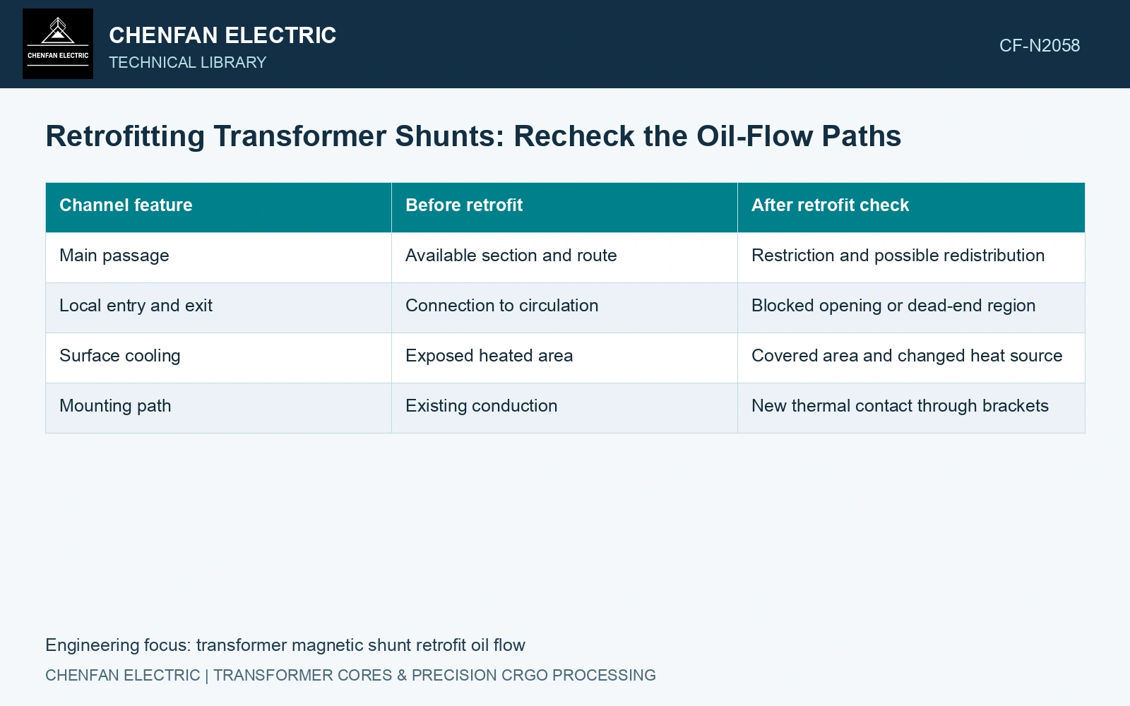
Map the passages before and after
Identify the shunt, brackets, fasteners and surrounding channels. Record the smallest relevant passages, openings at the top and bottom, bypass routes and connections to the larger oil circulation path. A local gap width alone does not describe whether oil can enter, pass through and leave. [1]
Retain construction tolerance and installed alignment. A nominal passage may narrow at a bracket or an uneven wall. Inspect the actual retrofit envelope rather than modelling only the magnetic packet.
| Channel feature | Before retrofit | After retrofit check |
|---|---|---|
| Main passage | Available section and route | Restriction and possible redistribution |
| Local entry and exit | Connection to circulation | Blocked opening or dead-end region |
| Surface cooling | Exposed heated area | Covered area and changed heat source |
| Mounting path | Existing conduction | New thermal contact through brackets |
Recalculate branch flow in the revised oil network
For an illustrative unchanged volumetric flow, reducing a channel area from 0.004 m² to 0.003 m² increases mean velocity by 0.004/0.003, or one third. This is continuity arithmetic under an assumed constant flow. An actual retrofit changes resistance and can redistribute flow between branches, so that assumption is not a thermal prediction.
Use a resolved flow model or a justified system representation where circulation changes matter. If the assessment uses convection coefficients, explain their evidence and whether the changed passage invalidates them. Retaining the old coefficient on a newly obstructed surface can conceal the retrofit’s effect.
Relocate the heat sources as well
Transfer the candidate’s tank, shunt and support losses into their actual locations. Lower tank power does not mean lower total local heat: the new shunt dissipates power and may collect it near a restricted passage. Update temperature-dependent properties where relevant.
Transfer electromagnetic losses to the thermal model by their physical location. If temperature changes a relevant material property, include that feedback in the solution. A magnetic field benchmark supplies neither this retrofit’s circulation nor its heat-transfer boundaries. [2]
Continue the assumed continuity screen with 0.006 m³/s total flow: mean velocity is 1.5 m/s through 0.004 m² and 2.0 m/s through 0.003 m². If local loss coefficient is assumed unchanged at 2.0 and oil density at 850 kg/m³, dynamic pressure loss Kρv²/2 rises from 1,912.5 Pa to 3,400 Pa, a 77.8% increase. The pump or buoyancy loop may not sustain the assumed flow. Re-solve the connected hydraulic network before crediting the retrofit with additional cooling; higher velocity in an artificially fixed-flow model can conceal reduced branch supply.
Compare the highest temperatures and their locations before and after the complete retrofit. A satisfactory result includes the newly shielded wall and any region whose oil access changed. The electromagnetic improvement is only one input to that decision.
References
- U.S. Department of Energy, DOE-HDBK-1012/3-92, Thermodynamics, Heat Transfer, and Fluid Flow, Volume 3, 1992.
- Z. Jurković, B. Jurišić and T. Župan, Multi-Step Approach for Fast Calculation of Magnetic Field in Transformer Tank Shields, Energies 17, 1378, 2024. DOI: 10.3390/en17061378.