

Tank-mounted shunts require a load path from electromagnetic traction into brackets and packet restraints. This note demonstrates a force-to-support calculation and identifies the additional data needed for a fault qualification.
Choose the force formulation correctly
J × B represents force on free conductor current; it alone is not a complete force model for a magnetizable packet. Pineda-Arciniega et al. integrate Maxwell stress on a boundary and pass the resulting load into a structural model [1]. Their example is a DC actuator, not a fault-loaded transformer shunt.
A total force obtained on an enclosing surface does not uniquely determine the internal body-force distribution in the laminated packet. Resolving that distribution requires a suitable material and coupled formulation. Do not turn a total-force result into an invented uniform volume load and present the resulting local stress as fully validated.
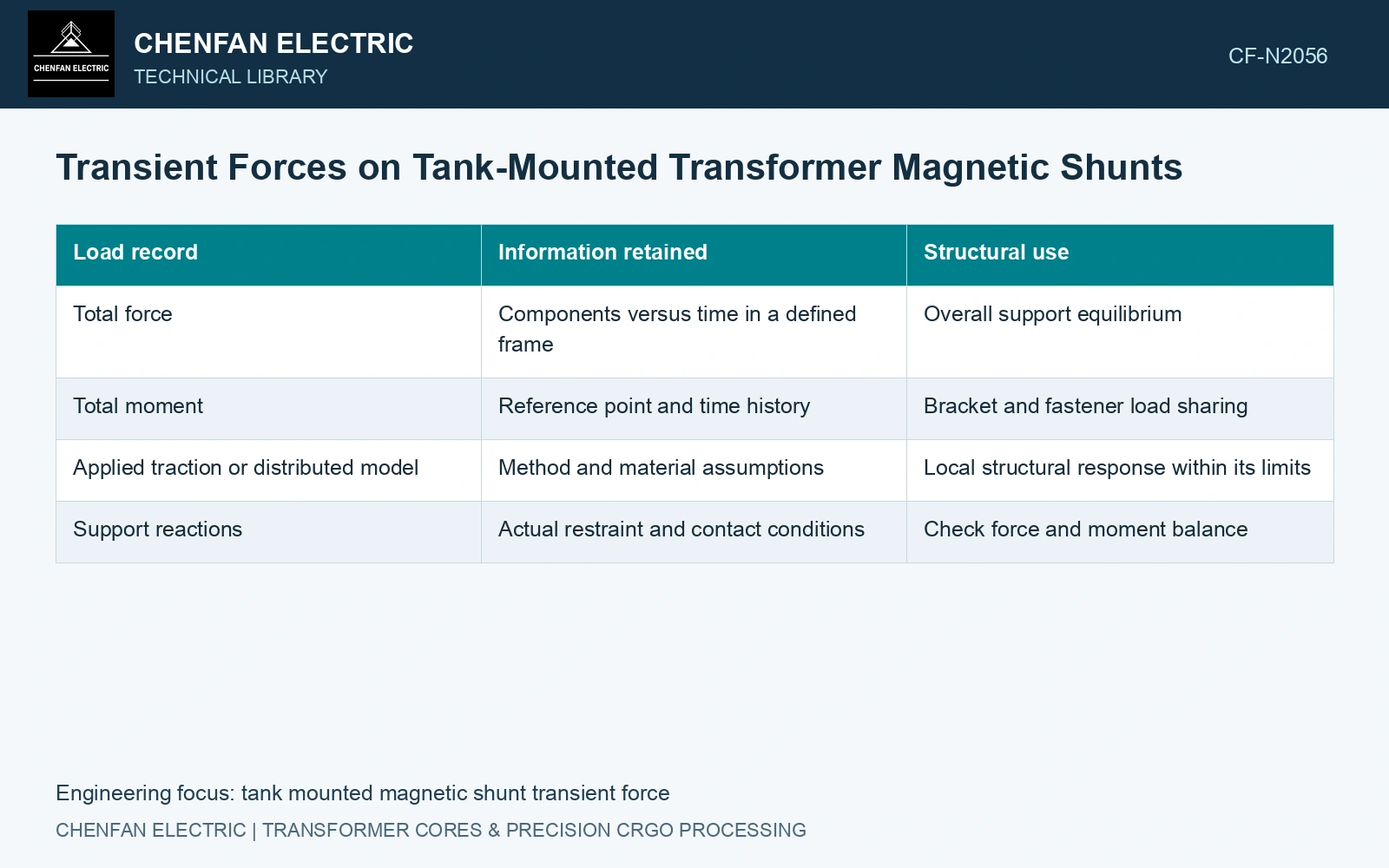
Build a support-load map
| Load record | Information retained | Structural use |
|---|---|---|
| Total force | Components versus time in a defined frame | Overall support equilibrium |
| Total moment | Reference point and time history | Bracket and fastener load sharing |
| Applied traction or distributed model | Method and material assumptions | Local structural response within its limits |
| Support reactions | Actual restraint and contact conditions | Check force and moment balance |
Check numerical convergence of the total force and its sensitivity to the integration surface or formulation. Avoid double-counting Lorentz force if the selected total-force method already includes it. Retain the coordinate transformation when loads are passed into the structural model.
Compare static and dynamic response
A slowly changing load may permit a quasi-static structural assessment. A fast pulse can excite the packet and supports. Compare the load time scale with the relevant structural response and use a justified dynamic model where required.
Include actual mounting stiffness, restraint, mass and contact behaviour. A perfectly fixed bracket assumption can hide deformation or alter the load sharing. A simple current-squared scaling is limited to a suitable linear magnetic regime; saturation can change the force trajectory and location.
Keep each acceptance question visible
Check fastener reactions, bracket deformation, packet movement and affected clearances. The tank-shield field benchmark supplies no fault-force waveform or support test [2].
For an independent teaching model, assume uniform normal air-side B over area A = 0.010 m², negligible tangential field, and μ₀ = 4π × 10⁻⁷ H/m. Maxwell pressure gives F = AB²/(2μ₀): 159.15 N at assumed 0.20 T and 636.62 N at 0.40 T [1]. Assume the latter is a rectangular 2 ms force pulse on an initially stationary, undamped single-degree support with natural frequency 100 Hz. Its maximum post-pulse spring reaction is 2F sin(πfₙtₚ) = 748.39 N, exceeding an assumed 500 N review cap; static screening alone gives 636.62 N. Reject that teaching support. For a real packet, obtain nonuniform field traction, force/moment history, contact restraints and damping before applying any support limit.
Deliver the source waveform, total force and moment, distributed-load assumptions and resulting support reactions. These records establish the mechanical conclusion alongside its thermal counterpart.
References
- M. Pineda-Arciniega, M. A. Arjona, C. Hernandez and R. Escarela-Perez, Numerical Modeling and Analysis of an Electromagnetic Device Using a Weakly Coupled Magnetostatic-Mechanical Formulation and the 2D Finite Element Method, Energies 16, 2182, 2023, section 2.2. DOI: 10.3390/en16052182.
- Z. Jurković, B. Jurišić and T. Župan, Multi-Step Approach for Fast Calculation of Magnetic Field in Transformer Tank Shields, Energies 17, 1378, 2024. DOI: 10.3390/en17061378.