

Tank-wall permeability can govern a shielding model’s predicted field and loss. Use traceable material input and sensitivity checks to establish the operating range in which the chosen approximation supports the design.
Identify what the curve represents
Record tank-steel identity, specimen direction, temperature, preparation and the measurement basis of the magnetization curve. Ask whether the evidence represents the relevant forming or welding condition, or only the original sheet. A curve for a different steel or processing state is a surrogate requiring an explicit limit.
Secant permeability, represented by B/H at a point, differs from incremental permeability, represented by the local slope dB/dH. They answer different modelling questions. Substituting one scalar into a formulation intended for the other can change the predicted response even when both numbers appear plausible.
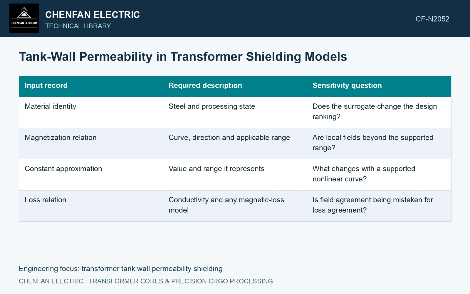
| Input record | Required description | Sensitivity question |
|---|---|---|
| Material identity | Steel and processing state | Does the surrogate change the design ranking? |
| Magnetization relation | Curve, direction and applicable range | Are local fields beyond the supported range? |
| Constant approximation | Value and range it represents | What changes with a supported nonlinear curve? |
| Loss relation | Conductivity and any magnetic-loss model | Is field agreement being mistaken for loss agreement? |
Keep the constitutive and loss models distinct
A B–H curve helps describe magnetization. It does not automatically provide hysteresis loss under the applied waveform. Conductive loss also depends on the current distribution and electrical properties. State which contributions are resolved, estimated or omitted.
The multi-step tank-shield study uses nonlinear shield material while simplifying selected source-transfer stages [1]. The bushing-region study instead solves a defined conductor/tank problem with constant tank permeability [2]. Neither establishes the magnetization curve of another fabricated tank steel.
Test the decisions sensitive to the input
Vary the material description within an evidence-based range and inspect tank field, shunt loading, integrated losses and local concentrations. Avoid an arbitrary enormous permeability sweep that creates physically irrelevant alternatives. If the preferred shunt location or thickness changes within the credible range, obtain better material evidence before relying on the original ranking.
Check model convergence and the treatment of the wall thickness relative to penetration depth. A boundary approximation has its own applicability limits; changing permeability can also change whether that approximation remains suitable.
Assume a 0.010 m tank wall, conductivity 6.0 MS/m and a 50 Hz field for a linear skin-depth screen. Relative permeabilities assumed as 100 and 1,000 give skin depths √[1/(πfμ₀μᵣσ)] of 2.91 mm and 0.919 mm. Their thickness/skin-depth ratios are 3.44 and 10.88. One arbitrary constant permeability therefore changes the screening regime considerably. Use measured or justified nonlinear material behaviour over the actual field range, and test sensitivity of local field and losses rather than choosing permeability only to match a total-loss result.
Report the input curve or approximation, the regions operating near its limit and the resulting decision sensitivity. A design that passes across the supported material variation carries a different level of evidence from one whose apparent benefit depends on a single unverified permeability.
References
- Z. Jurković, B. Jurišić and T. Župan, Multi-Step Approach for Fast Calculation of Magnetic Field in Transformer Tank Shields, Energies 17, 1378, 2024. DOI: 10.3390/en17061378.
- S. Khan et al., Computation of Stray Losses in Transformer Bushing Regions Considering Harmonics in the Load Current, Applied Sciences 10, 3527, 2020. DOI: 10.3390/app10103527.