

Lead-exit shielding depends on the physical paths of all three phase conductors. Calculate their local field around the aperture under the relevant phase conditions to establish coverage and heating duty. [1] [2]
Reconstruct the lead geometry
Map the current-carrying paths, phase identities, spacing, bends and return routes near the tank. Include the actual aperture shapes and nearby mounting metal. A straight-lead simplification should state which bends and connections it omits and whether they are remote from the region of interest.
Retain phase angle and spectrum for each relevant current. A magnitude-only combination loses the timing and direction of field contributions. At a selected point, calculate or measure the vector field resulting from the actual conductors rather than multiplying one isolated-conductor result by three.
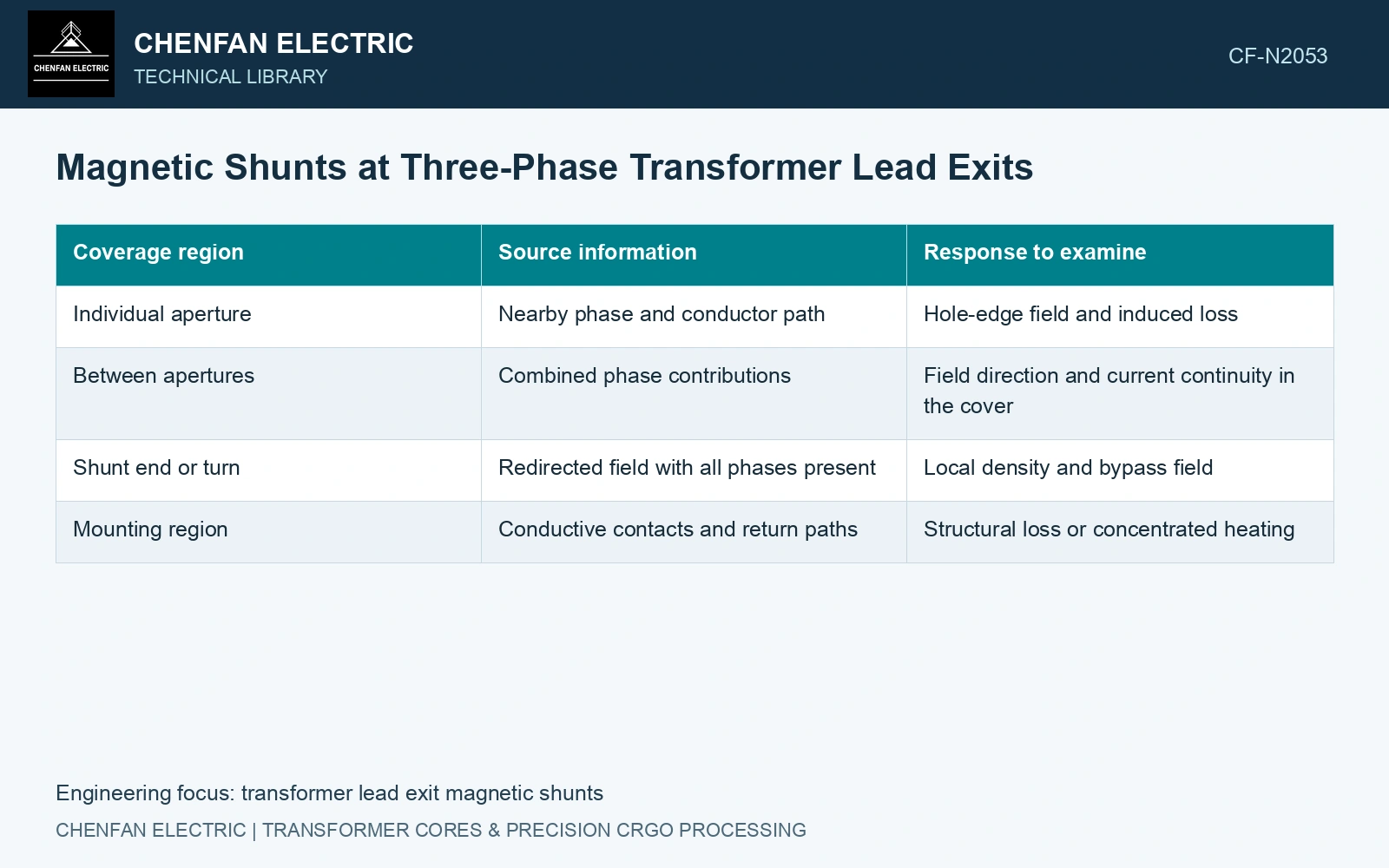
| Coverage region | Source information | Response to examine |
|---|---|---|
| Individual aperture | Nearby phase and conductor path | Hole-edge field and induced loss |
| Between apertures | Combined phase contributions | Field direction and current continuity in the cover |
| Shunt end or turn | Redirected field with all phases present | Local density and bypass field |
| Mounting region | Conductive contacts and return paths | Structural loss or concentrated heating |
Respect the simplified model’s boundary
The published bushing-region harmonic study considers a single axial conductor passing through a disk-shaped tank region with constant permeability. It compares its analytical solution with finite-element simulation and explicitly leaves three-phase conductors for further development. It supports the mechanism and frequency concern, not a ready-made three-phase shield layout. [2]
Independent phase or harmonic superposition requires an appropriate linear formulation. If the magnetic shunt enters a strongly nonlinear range, solve the coupled condition or use a justified approximation rather than adding separate saturated results.
Inspect the aperture and the redirected path
Compare the unshielded and proposed arrangements with the same source geometry. Retain the cover’s loss map, shunt loading and local thermal response. A shunt can lower field beside one aperture while concentrating it at an end or an adjacent unprotected opening.
Keep this magnetic assessment separate from bushing electric-field grading and dielectric clearance. A lower magnetic loss does not establish insulation coordination.
For an independent free-air screen, assume three infinite parallel z-directed leads at x = −0.10, 0 and +0.10 m, y = 0. Their RMS currents are 1,000∠0°, 1,000∠−120° and 1,000∠+120° A. At point (0, 0.10 m), sum each lead’s field using Bx = −μ₀IΔy/(2πr²) and By = μ₀IΔx/(2πr²). With μ₀ = 4π × 10⁻⁷ H/m, the totals are Bx = (0.500 + j0.866) mT and By = (1.500 − j0.866) mT; √(|Bx|² + |By|²) = 2.000 mT RMS. Zero phasor current sum has not cancelled the local field. Retain all three paths in the aperture model. Steel, bends and shield nonlinearity are omitted here, so this result selects the required model coverage rather than predicting tank heating.
The useful coverage drawing identifies the conductor paths, phase conditions and regions whose field or heating controls the decision. It should remain traceable to the actual lead-exit arrangement rather than to an ideal balanced sketch.
References
- Z. Jurković, B. Jurišić and T. Župan, Multi-Step Approach for Fast Calculation of Magnetic Field in Transformer Tank Shields, Energies 17, 1378, 2024. DOI: 10.3390/en17061378.
- S. Khan et al., Computation of Stray Losses in Transformer Bushing Regions Considering Harmonics in the Load Current, Applied Sciences 10, 3527, 2020. DOI: 10.3390/app10103527.