

Copper shields oppose an incident field through induced currents; CRGO shunts redirect magnetic flux [1]. Compare their combination with each single measure using a common loss boundary.
Keep a common loss boundary
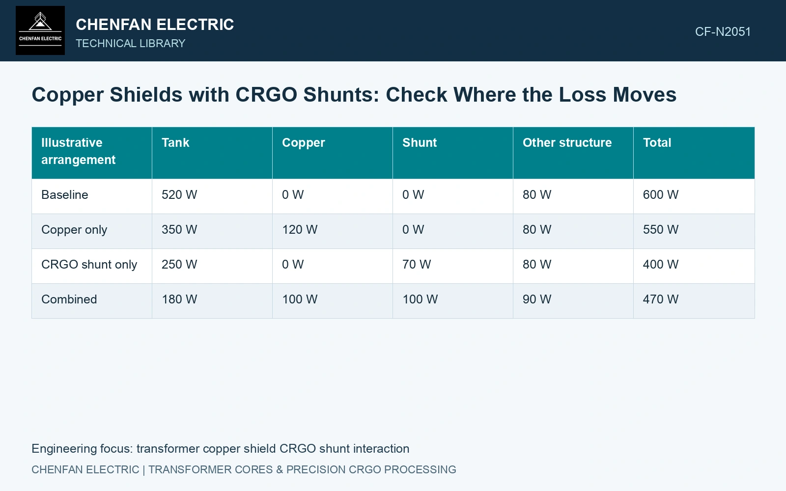
Compare baseline, copper-only, shunt-only and combined arrangements at the same source and temperature basis. Include the tank, added shields and nearby metal; identify unchanged losses excluded from the comparison.
| Illustrative arrangement | Tank | Copper | Shunt | Other structure | Total |
|---|---|---|---|---|---|
| Baseline | 520 W | 0 W | 0 W | 80 W | 600 W |
| Copper only | 350 W | 120 W | 0 W | 80 W | 550 W |
| CRGO shunt only | 250 W | 0 W | 70 W | 80 W | 400 W |
| Combined | 180 W | 100 W | 100 W | 90 W | 470 W |
All values are fictional. The separate savings are 50 W and 200 W. Adding them would predict 350 W for the combined total, whereas the illustrative coupled result is 470 W. The tank dissipates less power, but the combined structural total exceeds the shunt-only total. This example demonstrates the accounting question, not an expected production outcome.
Find the interaction
Inspect current distribution in the copper and flux density in the shunt with both devices present. Check whether the copper redirects field into the shunt ends, whether the shunt changes the plate’s current loops and whether mounting introduces new connections.
Use compatible material and loss formulations. The multi-step shunt method primarily calculates magnetic fields [2]; the copper’s induced currents and dissipation require additional physics. Benchmarking the shunt field does not validate that combined loss solution.
Follow the temperature distribution
Transfer each component’s spatial loss into the thermal model. Lower total power can still produce a higher local temperature if it moves into a poorly cooled region. Compare copper edges, shunt ends, tank features and supports rather than inspecting only the original tank hot spot.
Update conductivity and relevant magnetic properties if temperature changes them enough to alter the conclusion. The structural-loss review discusses electromagnetic–thermal interaction [1]; a fixed-property calculation needs an explicit supported temperature range.
Select the arrangement on combined loss, governing local temperatures and construction cost. Add the second measure when its resolved improvement over the best single measure justifies the added material and interfaces.
References
- S. Mikulić and D. Žarko, Stray Losses in Structural Components of Power Transformers, Energies 19, 322, 2026, sections 3.1 and 3.5. DOI: 10.3390/en19020322.
- Z. Jurković, B. Jurišić and T. Župan, Multi-Step Approach for Fast Calculation of Magnetic Field in Transformer Tank Shields, Energies 17, 1378, 2024. DOI: 10.3390/en17061378.