

Shunt-pack insulation must control complete current paths through edges, cut faces and mounts. Map those connections against the leakage field to establish which assembly bridges affect loss and heating. [1] [2]
Draw the complete conductive return paths
Identify possible bridges between sheets at cut edges, damaged coating, conductive debris, fasteners and supports. Trace a return path for each candidate loop. One local connection may be part of a larger distributed circuit; it is not, by itself, enough information to calculate circulating current.
Keep currents within a single sheet distinct from circuits crossing several laminations. Interlaminar insulation can interrupt cross-sheet paths, but it does not eliminate in-plane eddy currents. Leakage-field direction matters: a component normal to a broad sheet can link a different current path from flux running mainly along it.
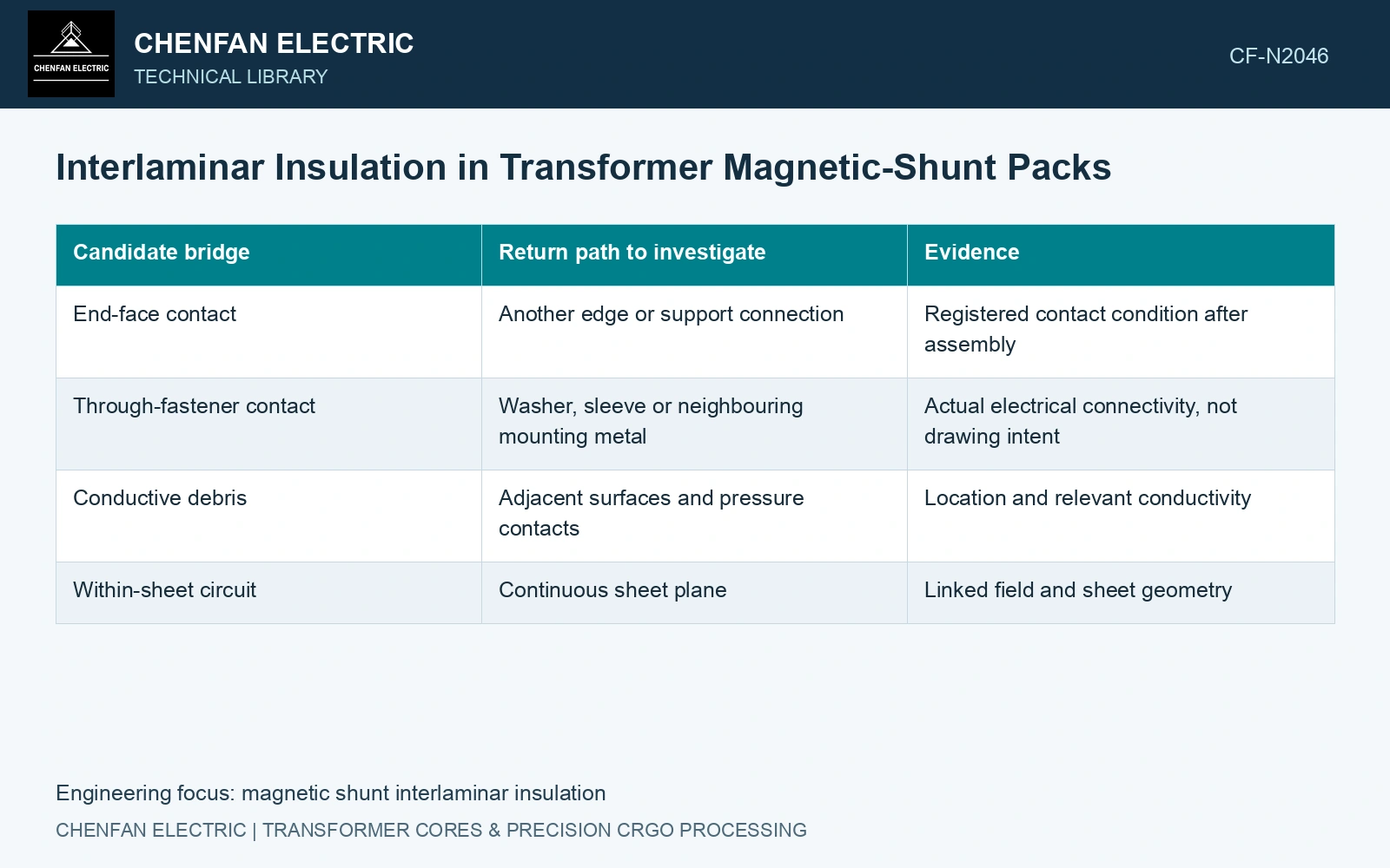
| Candidate bridge | Return path to investigate | Evidence |
|---|---|---|
| End-face contact | Another edge or support connection | Registered contact condition after assembly |
| Through-fastener contact | Washer, sleeve or neighbouring mounting metal | Actual electrical connectivity, not drawing intent |
| Conductive debris | Adjacent surfaces and pressure contacts | Location and relevant conductivity |
| Within-sheet circuit | Continuous sheet plane | Linked field and sheet geometry |
Test the assembled condition
Evaluate electrical connections under representative restraint and mounting conditions. A loose pack can differ from the installed assembly. Keep the test method, contact pressure and sampled area explicit; a broad surface measurement can miss a localized edge connection.
If modelling the loop, include its actual conductive topology and the linked time-varying field. A homogenized anisotropic conductivity can represent a qualified average behaviour, but it may omit a discrete bridge. Conversely, treating the pack as one conducting solid can invent paths that intact insulation prevents.
Look for local heat and loss
Compare the suspected bridge region with a suitable insulated control under the same source field. Retain local temperature and electrical or magnetic evidence where practical. A hot area can have several causes, and an infrared image alone does not identify the circuit.
The cited shield-field method is primarily magnetostatic and does not calculate internal eddy-current loss. Its accurate field prediction within its benchmark cannot validate the current topology of a shorted pack. That requires an additional electrical-loss assessment.
For a non-standard teaching witness, assume two sheets at specified contact pressure give 100 Ω under 1 V DC: leakage is 10 mA. A damaged witness gives 10 Ω and 100 mA under the same conditions. Against an assumed witness-screen cap of 20 mA, the first passes and the second fails. These values are not an IEC 60404-11 procedure or limit [2]. Hold the damaged process state for investigation, then test the assembly under its agreed insulation specification. DC leakage cannot be converted directly into operating watts because AC loop geometry and induced voltage differ.
Set the insulation requirement from the shunt geometry, field and assembly risk. Link each relevant bridge to its current-path and thermal consequences when defining acceptance.
References
- Z. Jurković, B. Jurišić and T. Župan, Multi-Step Approach for Fast Calculation of Magnetic Field in Transformer Tank Shields, Energies 17, 1378, 2024. DOI: 10.3390/en17061378.
- IEC, IEC 60404-11:2021, Magnetic materials — Part 11: Methods of measurement of the surface insulation resistance of electrical steel strip and sheet.