

A shunt fastener changes magnetic section and electrical connectivity. The structural-loss review describes heat from circulating currents through mechanical connections [1]. Treat hole, bolt, sleeve, washers and bracket as one assembly.
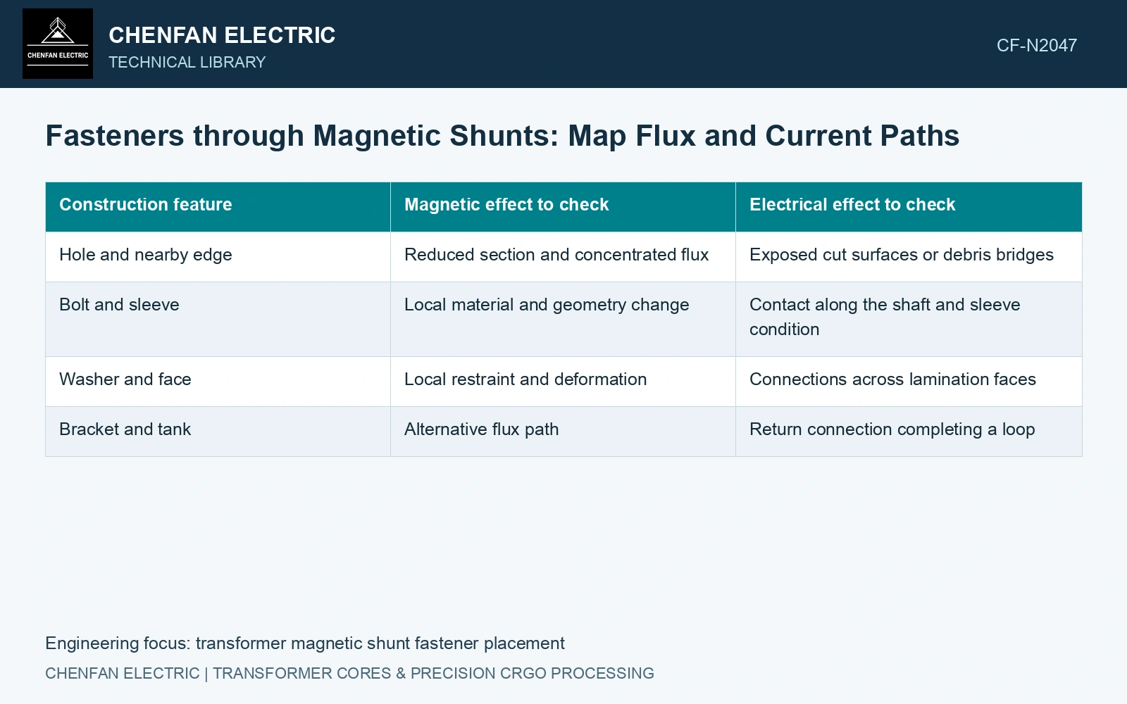
Map the magnetic interruption
Place the hole on the local flux map. Identify the steel section removed normal to the relevant internal flux and the routes available around it. A hole in a lightly loaded region and the same hole near a concentrated end flux are different conditions.
Examine local crowding with the actual hole, edge radii and material direction. Do not calculate a new mean density from net area and assume it describes the maximum around the hole. Nonlinear redistribution can concentrate flux on one side more than another.
| Construction feature | Magnetic effect to check | Electrical effect to check |
|---|---|---|
| Hole and nearby edge | Reduced section and concentrated flux | Exposed cut surfaces or debris bridges |
| Bolt and sleeve | Local material and geometry change | Contact along the shaft and sleeve condition |
| Washer and face | Local restraint and deformation | Connections across lamination faces |
| Bracket and tank | Alternative flux path | Return connection completing a loop |
Trace the complete conductive circuit
Follow the path from one lamination or packet through every contacting item and back through the surrounding assembly. A conductive connection matters through the flux linked by the resulting circuit. It cannot be assessed from the fastener’s presence alone.
Check the as-built interface after tightening. A sleeve can be displaced or a washer can contact an unintended edge. Conversely, a magnetic contact that changes reluctance does not necessarily create an electrical connection through an intact insulating layer.
Evaluate local mechanical and thermal consequences
Retain actual restraint and contact. Tightening can change stress, packet shape and oil access. A lower tank field does not establish acceptable fastener temperature if the fastener or its return dissipates additional power. [1]
Use an eddy-current and thermal assessment for a relevant conductive loop. A magnetic section calculation alone cannot qualify the installed fastening topology or heating.
Assume a fastener bridges insulated packet faces with resistance 0.020 Ω, while another 0.020 Ω contact closes a loop driven by assumed 0.20 V RMS. Neglecting reactance gives I = 5 A and total I²R = 1 W [2]. A mechanically suitable insulated assembly opens the loop only if sleeves, washers and frame contacts preserve separation. Verify the installed circuit and separately solve the hole’s magnetic perturbation; the fastener’s material label proves neither result.
Compare mounting constructions under the same source and structural duty. Verify the installed hole region and complete return path, including every interface that makes the fastener insulation effective.
References
- S. Mikulić and D. Žarko, Stray Losses in Structural Components of Power Transformers, Energies 19, 322, 2026, sections 3.1 and 3.5. DOI: 10.3390/en19020322.
- U.S. Department of Energy, DOE-HDBK-1011/4-92, Electrical Science, Volume 4, 1992.