

Step-lap tip loading depends on contact area, support and lever arm. Use the local geometry to design a representative damage-boundary test before selecting a robot force limit. [1]
Locate the contact and its support
Mark where the tool or incoming lamination first touches, where the underlying layer supports it and which portion remains free. Distinguish a touch used to establish position from a load intended to flatten or seat the sheet. They can follow different force-displacement paths.
A force acting through a lever arm produces a bending moment, while contact pressure also depends on the effective area. Neither is determined by force magnitude alone. A narrow tip can experience a different local condition even when the robot reports the same total load as on a broad yoke surface.
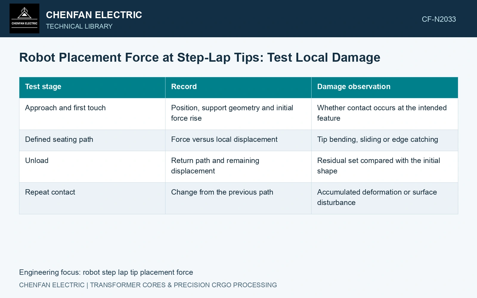
Record a controlled contact path
| Test stage | Record | Damage observation |
|---|---|---|
| Approach and first touch | Position, support geometry and initial force rise | Whether contact occurs at the intended feature |
| Defined seating path | Force versus local displacement | Tip bending, sliding or edge catching |
| Unload | Return path and remaining displacement | Residual set compared with the initial shape |
| Repeat contact | Change from the previous path | Accumulated deformation or surface disturbance |
Use representative sacrificial parts under an approved test procedure. Cover the relevant gauge, tip length, cut geometry and support condition. Retain the local displacement measurement rather than interpreting robot-axis movement as tip deflection; tool and robot compliance can consume part of that movement.
Check the measurement chain
Identify the force reference frame, sensor location, zero condition and contributions from tool weight or acceleration. A transient force peak may reflect motion as well as contact. Synchronize force with the local geometry observation and confirm that sampling captures the relevant event.
NIST robot-metrology work shows that loading and structural deflection can affect the tool pose. That supports checking the complete measurement and support chain. It does not provide a damage threshold for a GOES tip. [1]
Choose the boundary from the recovered part
Assess unloaded tip shape and the contact surface after each defined path. A return of total tool force to zero does not prove elastic recovery of the sheet. Likewise, a force-displacement kink may indicate sliding or a changed support rather than metal yielding.
Use catalogue thickness 0.23 mm [2]. An assumed 10 N force over 2 × 5 mm gives nominal pressure 1 MPa; over 10 × 10 mm it gives 0.10 MPa. Now assume the narrow contact loads a 5 mm-wide tip with a 2 mm unsupported lever arm. The elastic beam stress screen σ = 6FL/(bt²) gives 453.7 MPa. That figure is not a reliable yielded-state prediction or a GOES allowable; it shows why broad-pad pressure qualification cannot qualify the unsupported tip. Measure unloaded residual set, coating damage and magnetic change on the actual cut/coated witness, then establish a force envelope for that support geometry.
Tip support, gripper compliance, approach angle and local contact footprint control damage. Preserve the actual coated sheet and cut-edge state in qualification, then link the force envelope to that geometry.
Set the production contact condition below a justified damage boundary, with the appropriate uncertainty and variation allowance established by the engineering team. Qualify it for the stated part and support family. When the tip geometry or underlying support changes, the old tool-force number needs renewed evidence.
References
- G. Qiao and B. A. Weiss, Industrial Robot Accuracy Degradation Monitoring and Quick Health Assessment, Journal of Manufacturing Science and Engineering 141, 2019. DOI: 10.1115/1.4043649.
- Nippon Steel Corporation, Grain-Oriented Electrical Steel Sheets, catalogue D004je, April 2020, specification and typical-property tables.