

A wide-strip laser process needs a focus map across the complete working width. Optical geometry and strip height change the working distance, so edge and centre results belong in the same qualification.
Map the two surfaces that define focus
Use a strip-fixed transverse coordinate y and a common height reference. At each station, record the material surface height and the qualified optical working-distance definition. The relative difference is the focus error of interest. Comparing a strip-height map with a focal-plane map referenced to another origin can create a false drift.
Measure or otherwise establish the beam dimensions at representative stations using the approved optical method. Record the spot definition and intensity distribution. A nominal focal distance does not establish the actual footprint across the scan field, especially where incidence and spot orientation change.
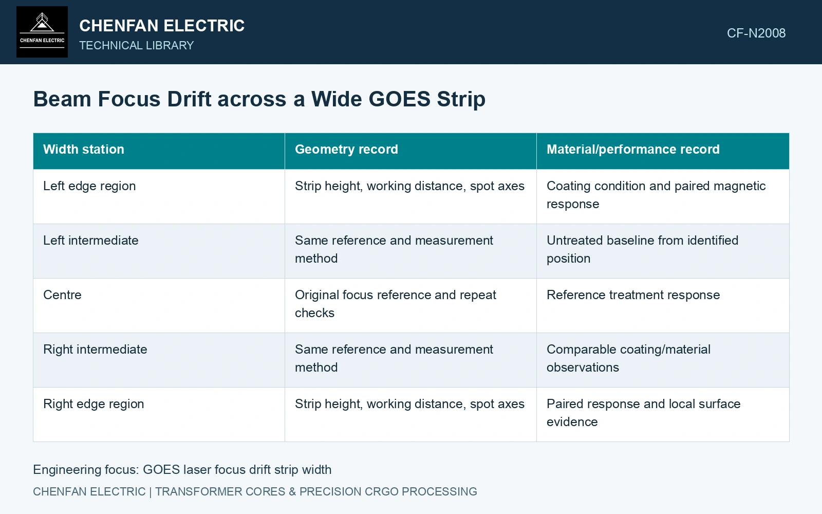
| Width station | Geometry record | Material/performance record |
|---|---|---|
| Left edge region | Strip height, working distance, spot axes | Coating condition and paired magnetic response |
| Left intermediate | Same reference and measurement method | Untreated baseline from identified position |
| Centre | Original focus reference and repeat checks | Reference treatment response |
| Right intermediate | Same reference and measurement method | Comparable coating/material observations |
| Right edge region | Strip height, working distance, spot axes | Paired response and local surface evidence |
Separate the native strip gradient
Take identified untreated and treated material at comparable width positions. A lower-quality edge before treatment cannot establish that the laser created the final edge-to-centre difference. Use the local change, with its uncertainty, alongside the absolute final value.
For an illustrative bookkeeping definition, Δp(y) = ptreated(y) − pcontrol(y), where both specific losses are in W/kg at the same induction, frequency and waveform. A negative difference indicates lower measured loss under those conditions. It is not automatically the treatment effect if the samples differ in native material or preparation.
Coating optical response can also vary with position. Inspect that boundary before increasing power at an edge to compensate for an assumed defocus. The same adjustment can mask a material difference or create a new surface problem. [1]
Use a controlled intervention
Repeat the width map after a justified focus correction while retaining the material and energy basis. If the optical footprint becomes more consistent but the magnetic gradient remains, investigate coating and native structure rather than continuing to tune focus. If the gradient moves with strip height changes, the working-distance representation needs attention.
Do not assume a larger spot always produces a poorer magnetic result or a safer coating condition. Redistribution of intensity, dwell and absorbed input can have competing effects. Verify magnetic and surface outcomes at each consequential station.
The catalogue thickness of 0.23 mm is not a flatness tolerance. [2] Assume a wide strip has a 0.30 mm centre-to-edge height change and a tested optical working envelope of ±0.10 mm around focus. Focusing at the centre leaves the edge 0.30 mm away, three times that allowed offset. Recentring focus halfway between extremes leaves ±0.15 mm and still fails. Use active height/focus control or revise strip support, then compare track and magnetic uniformity; moving the nominal focal plane cannot close an envelope wider than the qualified depth range.
Strip flatness, support roll condition, thermal bow and scan-field focus correction control the local working distance. Include the actual moving-strip profile rather than qualifying the beam on a stationary flat coupon.
Cover the ordered strip width with position-specific optical and magnetic evidence. Use the resulting map to set a focus tolerance that controls delivered material at both the centre and edges.
References
- P. Rauscher et al., The influence of laser scribing on magnetic domain formation in grain oriented electrical steel visualized by directional neutron dark-field imaging, Scientific Reports 6, 38307, 2016, Table 1. DOI: 10.1038/srep38307.
- Nippon Steel Corporation, Grain-Oriented Electrical Steel Sheets, catalogue D004je, April 2020, specification and typical-property tables.